Memory for AI: Two Edges and a Roofline

This article is part of our Library Series: System Design: Memory for AI
What you’ll learn:
- How the roofline model can provide insights into AI architecture’s compute performance.
- The best way to ensure AI applications operate at peak performance on their processors.
In Part 2 of this series, we examined the virtuous cycle created by the need for more data to make AI better, and the ever-increasing amount of digital data in the world. Moreover, we provided an analysis of how the impending 5G revolution will push more processing to the edge, and how the industry is fine-tuning the network from near edge (closer to the cloud) to the far edge (closer to the endpoints).
We expect to see a full range of AI solutions from endpoints to the network core, which will be differentiated in large part by the memory being used. The near edge will see AI solutions and memory systems that resemble those in cloud data centers today. Memory systems for these solutions will include high-bandwidth memories like HBM and GDDR. AI memory solutions at the far edge will be akin to those deployed in endpoint devices: on-chip memory, LPDDR, and DDR.
Oftentimes, the choice of memory depends on its potential application and the bandwidth required of it. In this article, we’ll explore how the Roofline model can help determine whether certain AI architectures are limited by their compute performance or by their memory bandwidth. The Roofline model reveals how an application performs on a given processor architecture by plotting performance (operations per second) on the y-axis against the amount of data reuse (operational intensity) on the x-axis.
Operational Intensity
The operational intensity of an application measures how many times each piece of data is used for computation once it’s brought in from the memory system. An application with high operational intensity reuses data multiple times in calculations after being retrieved from memory. Such applications are less demanding on their memory systems because less data needs to be retrieved from external memory to keep the compute pipelines full.
In comparison, applications with low operational intensity require more data to be retrieved from memory and require higher memory bandwidths to keep compute pipelines running at peak performance. In systems with low operational intensity, performance can often be bottlenecked by the memory system.
Roofline Model
The Roofline is unique to individual processor architectures and consists of two different line segments. The horizontal line represents the peak performance of the processors if every compute unit is running at full speed (see below). The sloped line, on the other hand, describes when the processor architecture is limited by memory bandwidth. The sloped line shows that as operational intensity (reuse) increases, compute units can perform more work, making it possible to achieve higher performance. With insufficient memory bandwidth, compute units have to wait for data from the memory system.
At the intersection of the two lines comprising the Roofline is the “Ridge Point,” which defines the lowest allowable operational intensity to maintain peak performance. This helps us understand how algorithms can be programmed to achieve peak performance for applications. The area underneath the solid green Roofline represents potential operating points for different applications. Some applications may not be able to reach the peak operating speed defined by the Roofline because of inefficiencies in the code, or insufficient resources in other parts of the system.
Due to the varying peak compute performance and memory system bandwidths provided by processor architectures, each has its own unique Roofline model. Plotting different applications against a Roofline curve provides one with a greater understanding of how applications behave on specific architectures.
For instance, we can see whether an application is limited more by peak performance of the processor or its memory bandwidth. In the figure, application No. 1 is nearer the sloped section of the Roofline. Based on its operational intensity, it’s limited more by memory bandwidth than anything else.
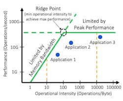
Application No. 3 lies underneath the flat part of the curve. This tells us that application No. 3 is instead limited more by the available compute resources in its processor than anything else. Improving the speed of the compute resources and/or adding more compute resources (for example, more adders and multipliers) would be one way to improve performance for application No. 3.
The horizontal and sloped parts of the Roofline meet near application No. 2. This tells us that application No. 2 is partially limited by memory bandwidth and partially limited by the performance of the processor’s compute resources. If additional computational resources and memory bandwidth were provided, application No. 2 could see performance improvements.
Conclusion
By utilizing the Roofline model, system designers are better able to plan how applications will perform on their processors and ensure they operate at peak performance. Understanding the behavior of target applications helps designers more accurately assess the type of memory to use in their system to achieve performance targets as well as trade off other characteristics like power and cost accordingly.
In the new era of AI, the importance of these insights can’t be overstated. Our next article will examine the Roofline model of certain AI applications, and how such models can be used to analyze machine-learning applications running on AI accelerators.
Read more articles from the Library Series: System Design: Memory for AI
About the Author

Steven Woo
Steven Woo is a Fellow and Distinguished Inventor at Rambus Inc., working on technology and business development efforts across the company. He is currently leading research work within Rambus Labs on advanced memory systems for data centers and AI/ML accelerators, and manages a team of senior technologists.
Since joining Rambus, Steve has worked in various roles leading architecture, technology, and performance analysis efforts, and in marketing and product planning roles leading strategy and customer programs. Steve received his PhD and MS degrees in Electrical Engineering from Stanford University, and Master of Engineering and BS Engineering degrees from Harvey Mudd College.
Comment About the Article
To join the conversation, and become an exclusive member of Electronic Design, create an account today!

Leaders relevant to this article: