A 555 Timer PWM Circuit to Control Ancient Evil
This article is part of the 2022 April 1st series in the Humor topic within our Series Library.
The ubiquitous 1971 digital miracle—the 555 Timer—is important, replete with 25 transistors, 15 resistors, and two diodes uncomfortably crammed into an IC smaller than a dime (5 pence coin for those across the pond). Just about anything can be made with a 555 Timer, and every circuit is fun to build, which I show in my book “Essential 555 IC: Design, Configure, and Create Clever Circuits.”
In the book, I walk the reader through the simplest use of a 555 timer to rather advanced techniques and tricks through the hands-on building of fun projects. But not every project made it to the book. In fact, a large swath of my manuscript’s goldenrod is still leveling my publisher’s desk.
However, I thought I would bring one of those cut projects here today, A gem for free! TODAY!
This one is simple for beginners, complex enough for the experienced, and essential in controlling an ancient evil.
A Little Background First
In this project, we’ll place the 555 timer into its “astable mode.” Also known as an astable multivibrator or a free-running multivibrator, in this mode the IC output is a continuous signal without the need for an external trigger.
In clearer terms, we’re going to create a pulse-width-modulation (PWM) signal using a 555 timer. This PWM signal can be used to apply a time indicating that something is activated, known as a duty cycle. For example, a 50% duty cycle will have the circuit load “on” for half the time.
In this project, we’ll apply a variable PWM signal to control the intensity of an ancient evil object. Increase the duty cycle time for more evil, decrease for less evil. In the old days, you might require shamans and trinkets of magical significance to have a similar effect. It’s 2022, not 2022 BC. It’s time for elegant technology to take over those old timeworn ways.
Let’s Look at the Schematic
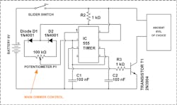
In a PWM circuit, the 555 timer will output a logic signal “high” and “low” depending on a ratio derived by the value of a few components connected. This is achieved through resistor R2, diodes D1 and D2, potentiometer P1, and capacitor C1 (Fig. 1).
For the sake of simplicity, I’ll reduce the equations down to what you need to know:
Time = Time On + Time Off
Duty Cycle = (Time On/Time)*100
Time On = 0.693*R2*C1
Time Off = 0.693*P1*C1
Therefore, the duty cycle will break down, in this case, to = R2/(R2+P1)
For instance, when P1 = R2, the duty cycle will be 50%. Or just half of the evil can pour out, clawing and ripping through surrounding objects.
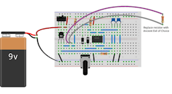
Let’s Build the Breadboard
Assemble as shown on a breadboard (Fig. 2). Take your time; one misplaced wire could mean centuries of darkness upon the lands.
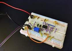
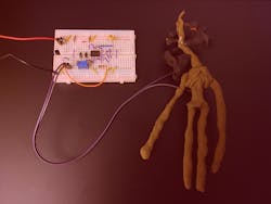
The final build should look something like Figure 3.
A Real-World Demo of the Circuit
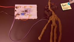
Now connect your circuit to the ancient evil. I chose this possessed figure, crafted by a blind limbless beast, during a violent storm, while on fire and underwater… a number of unspecified eons ago. How I came to acquire such an object is a story for another time. Here, I set the circuit at a very small duty cycle, about as far as I could crank that potentiometer with a wrench; I’m not messing around (Fig. 4). We want just a little bit of evil. You might feel a chill, or burning sensation, all over your body, but it should be tolerable.
The circuit cranked up to full-tilt boogie (Fig. 5). At this point, you might experience some eye bleeding, voices in your head, and/or the desire to decorate your lab with skeletons. Before the ancient evil-of-choice activates completely, I suggest just dialing that back down to a more moderate amount of heinous.

If you experience all of the above effects but now the is ground shaking—you’re cooked, my friend. As you’re being pulled into the bowels of uncertain doom, I at least hope you enjoyed this 555 timer tutorial.
If you survive… look forward to more unreleased 555 timer projects from me, such as:
- A 555 timer-based human heart pacemaker
- A 555 timer for a spinal-cord RC-controlled rabbit
- A monostable 555 timer weather manipulator
…and a recipe for a smooth and delightful 555 timer mojito. Get your ICs shaken, not stirred—the right way.
Your friendly neighborhood circuitman, Cabe Atwell.
Read more articles in the 2022 April 1st series in the Humor topic within our Series Library.
About the Author

Cabe Atwell
Technology Editor, Electronic Design
Cabe is a Technology Editor for Electronic Design.
Engineer, Machinist, Cartoonist, Maker, Writer. A graduate Electrical Engineer actively plying his expertise in the industry and at his company, Gunhead. When not designing/building, he creates a steady torrent of projects and content in the media world. Many of his projects and articles are online at element14 & SolidSmack, industry-focused work at EETimes & EDN, and offbeat articles at Make Magazine. Currently, you can find him hosting webinars and contributing to Electronic Design and Machine Design.
Cabe is an electrical engineer, design consultant and author with 25 years’ experience. His most recent book is “Essential 555 IC: Design, Configure, and Create Clever Circuits”
Cabe writes the Engineering Life & Engineering on Friday blog on Electronic Design.
See Cabe's cartoons & comic strips here.
Comment About the Article
To join the conversation, and become an exclusive member of Electronic Design, create an account today!

Leaders relevant to this article: