5 Tips for Improving Data-Center Flash Storage with EDSFF E1.S SSDs

Members can download this article in PDF format.
What you’ll learn:
- Why today’s 2.5-in. and M.2 form factors won’t suffice in next-generation data centers.
- Tips to improve data-center flash storage effectiveness with E1.S SSDs.
- E1.S SSD use-case examples.
Data storage based on 2.5-in. and M.2 drives is being pushed to its form-factor limits that directly affect its future use in data centers. The 2.5-in. format is based on legacy HDD form factors and can’t keep technological pace with the continuous advances surrounding faster networking protocols, memory bandwidth, and interconnect technologies, coupled with more robust SSD interfaces such as PCIe 4.0, 5.0, 6.0, and beyond. These limitations have created a need for a new form-factor architecture.
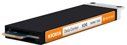
To address these form factor limitations, the SFF Technical Affiliate (SFF-TA) working group of the Storage Networking Industry Association (SNIA) architected E1.S form-factor specifications (Fig. 1).
E1.S form factors provide many benefits and capabilities beyond 2.5-in. and M.2 formats, and they’re designed specifically for flash-memory-based storage. They provide fast data input/output operations per second (IOPS) and low-latency performance when designed to the PCIe interface and NVMe protocol.
Here are five tips that can improve data-center flash-storage effectiveness with EDSFF E1.S SSDs:
1. Power-optimized support for up to 25-W power envelopes
The 2.5-in. form factor originated with HDDs and isn’t optimal for flash memory as it can’t scale beyond four PCIe lanes or enable full-throttle IOPS performance per terabyte (TB) of capacity, as it doesn’t support PCIe x8 or x16 link connections.
Performance of a typical M.2 (22110) SSD is 8.25 W (as of this publication), and this is apparent with higher capacities such as 4 TB and beyond. These SSDs can’t achieve full PCIe 4.0 (16 gigatransfers per second (GT/s) x4) bandwidth with this 8.25-W power envelope, and certainly not PCIe 5.0 (32 GT/s x4) or PCIe 6.0 (64 GT/s x4) bus saturation.
The E1.S form factor supports up to 25-W power envelopes for NVMe SSDs and can better saturate PCIe 4.0 (16 GT/s x4) links to improve data-center flash-storage performance effectiveness with better thermal characteristics.
2. Support for advanced thermal capabilities
SSDs require advanced thermal capabilities for continued operations despite varied temperature ranges. Both 2.5-in. and M.2 drives have thermal limitations. For example, M.2 SSDs don’t support internal heatsink options that enable selection of thermal profiles best suited to cool a system. Some lack thermal throttling mechanisms that detect when a drive has reached an operating temperature beyond its specification and will throttle performance, which reduces the heat generated from the flash memory.
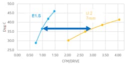
In some systems, 2.5-in. SSDs don’t provide optimal heat dissipation which limits overall airflow efficiency and heat dissipation within the data center. Airflow is based on Cubic Feet of air moved per Minute (CFM), so a form factor with better heat dissipation allows a system to operate at lower airflow levels.
The E1.S form factor supports internal heatsink options and thermal throttling capabilities for managing airflow and heat dissipation in high-temperature server environments. One of the main differences that set E1.S SSDs apart from 2.5-in. and M.2 drives is a significantly improved airflow design.
As PCB widths can make for an optimized flash-memory design, they’re smaller in E1.S SSDs and designed for efficient airflow. An E1.S SSD with a PCB width of 33.75 mm can move air much faster within a system than a standard 2.5-in. (U.2) drive and its low CFM (Fig. 2) may improve data-center flash-storage effectiveness.
3. Support for higher capacities per slot (vs M.2)
An M.2 SSD uses a 22-mm-wide PCB. At this width, flash-memory placements aren’t optimal and the potential for high drive capacities are limited.
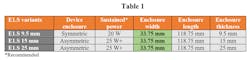
The E1.S form factor enables SSDs with 33.75-mm widths (Table 1), allowing for more space on the PCB for additional flash-memory chips. This capability can yield higher-capacity SSDs, provide more capacity per server slot, and improve data-center flash-storage density versus M.2 drives.
4. Support for hot swapping (vs M.2)
To replace a standard M.2 SSD, an entire server would normally need to be powered down. This is a time-consuming process that requires removing the system from the rack, as well as a few components (M.2 carrier card, external heatsink and M.2 SSD), and inserting a new M.2 SSD. Once this is completed, the entire assembly would need to be reconfigured.
The E1.S form factor enables supported SSDs to be hot swapped, including from the front of the server, without having to power it down. This provides time-saving, highly efficient physical serviceability that can reduce storage total cost of ownership (TCO) and improves data-center flash-storage effectiveness versus M.2 drives.
5. Support for next-generation technologies (vs. 2.5 in.)
The SFF-8639 connectors used with 2.5-in. SSDs aren’t designed to meet the signal-integrity challenges such as those that may be apparent in the upcoming PCIe 6.0 interface specification.
The E1.S form factor supports the next-generation PCIe 6.0 (64-GT/s x4 bandwidth) high-frequency interface through the E1.S connector system (SNIA SFF-TA-1002). The connector supports devices with link widths of PCIe x4 and x8 lanes, which improves data-center flash-storage effectiveness versus 2.5-in. drives.
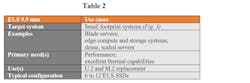
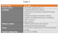
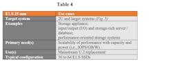
E1.S SSDs are targeted for the following use cases and servers (Tables 2, 3, and 4):

Standardized by OCP
For companies deploying hyperscale-type data-center architectures, the Open Compute Project (OCP) has specified systems and architectures similar to the largest hyperscalers. OCP took an open-source, collaborative approach to data-center issues and evaluated E1.S form factors for their ability to address a variety of storage challenges.
From its evaluation, OCP standardized on E1.S form factors developed by the SNIA SFF-TA working group and designed to the OCP Datacenter NVMe SSD specification for E1.S SSD design. Leading hyperscalers decided on E1.S designs, which in turn supports further adoption of the E1.S form factor, particularly for 1U deployments.
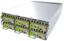
Yosemite V3 Flash Platform: SV7100G4
The OCP Yosemite V3 specification is a flash-storage platform built for Open Rack V2 server architectures (Fig. 6). The SV7100G4 platform is a highly modularized system built to support up to 48 E1.S 25-mm SSDs or up to 768-TB capacity per chassis.
A 40U system can carry 12 blades, enabling the entire rack to accommodate eight systems. Up to 96 servers in a rack can be accommodated, making the system a high-density, 2,496-core computing rack that’s ideal for hyperscale data centers.
Summary
E1.S form factors provide many benefits beyond 2.5-in. and M.2, including 25-W power envelopes, improved thermal performance and advanced thermal capabilities, more space for additional capacity (over M.2), hot swapping, and support for next-generation server and data-center designs.
For companies deploying PCIe 4.0 (or higher) storage with the NVMe protocol, the benefits of E1.S form factors are driving adoption. Additional industry support is coming from OCP and the UNH-IOL, which will soon conduct tests for OCP NVMe SSD-compliant drives.
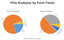
E1.S form factors are projected to grow from 1.8% of the total exabyte share of combined PCIe form factors in 2021 to 35.4% market share in 2026 (Fig. 7).
E1.S SSDs are designed for use cases such as small footprint and edge systems (E1.S 9.5 mm), 1U systems (E1.S 15 mm), and 2U and larger hyperscale-type systems (E1.S 25 mm), and include additional standards from OCP. Leading authors of the OCP Datacenter NVMe SSD Specification, Meta, and Microsoft may use E1.S SSDs on upcoming platforms and SSD suppliers were expected to provide E1.S-based SSDs in 2022.
Maulik Sompura is currently leading KIOXIA’s Data Center, Enterprise and Client SSD Product Strategy and Product Management teams. He has 15+ years of NAND flash memory and storage experience. With a strong technical background and key product insights, he’s led his teams to achieve tremendous growth in data center and client segments. He’s also been a close collaborator with hyperscalers spawning the OCP specification, helping to pioneer new technologies with industry partners.
References
SNIA: Webcast Panel Discussion, “Enterprise and Data Center SSD Form Factors – The end of the 2.5in disk era,” August 4, 2020, 11:00am PT, Slides 17, 24, and 32.
TrendFocus, PCIe Form Factor Comparison, by Exabytes, for 2021 to 2026.
About the Author
Maulik Sompura
Sr. Director of Product Management, SSD BU, KIOXIA America Inc.
Maulik Sompura is currently leading KIOXIA’s Data Center, Enterprise and Client SSD Product Strategy and Product Management teams. He has 15+ years of NAND flash memory and storage experience. With a strong technical background and key product insights, he’s led his teams to achieve tremendous growth in data center and client segments. He’s also been a close collaborator with hyperscalers spawning the OCP specification, helping to pioneer new technologies with industry partners.
Comment About the Article
To join the conversation, and become an exclusive member of Electronic Design, create an account today!

Leaders relevant to this article: