Achieving Bit-Perfect USB Audio
This file type includes high-resolution graphics and schematics when applicable.
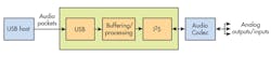
One popular approach taken to ensure high-quality audio streaming to external accessories is to use USB as an interface. The ability to plug your device into a universally available interface combined with pre-installed drivers makes using USB for audio applications very attractive. Despite these advantages, using the USB Audio class requires some clever system engineering to ensure there are no glitches, or worse, frequency mismatches when streaming. The article “Select your USB audio MCU with care: Scary stories from the test bench” offers an interesting look at failure cases.
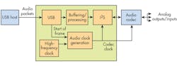
USB audio systems act as a serial bridge that translates packets from the USB bus to the Inter-IC Sound (I2S) bus. This bus is usually connected to a codec or audio processor downstream (Fig. 1). The tricky aspect with the I2S bus is the requirement for precise clocking to achieve high-quality audio.
To illustrate, a typical sample rate for audio is 48 ksamples/s. Most commercially available codec ICs require a clean clock that’s an integral multiple (typically 128x or 256x) of the audio sample rate. This puts the codec clock at a terrifyingly precise 12.288 MHz, which isn’t easy to derive off standard crystal clock sources. To add to the complexity, supporting multiple sample rates like 44.1 ksamples/s requires an equally high-quality clock for each sample rate. This means the system either needs multiple crystals or must employ some very flexible clocking.
It’s possible to use surface-mount-device (SMD) oscillators. However, these generally power-hungry devices require upwards of 20 mA, making them impractical for battery-powered devices. Flexible clocking can also be implemented using phase-locked loops (PLLs). The PSoC 4-L series of chips from Cypress, for example, integrate PLLs and highly configurable universal digital blocks (UDBs) to enable developers to design flexible clocking schemes.
Clocking Woes—the I2S Bus
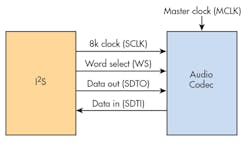
I2S is the standard interface used for transmitting audio between two chips. The protocol is similar to a serial peripheral interface (SPI) with a couple of extra signals. The nature of audio data, however, makes clocking the I2S bus harder than it looks. Figure 2 shows a typical I2S bus connection between a codec and the master chip.
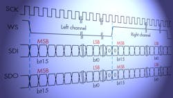
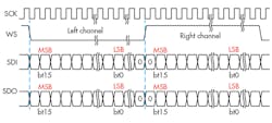
The I2S bus (Fig. 3) consists of:
• Bit clock: Clock for reading the data off the Data In and Out lines.
• Word select: Also called Left-Right Clock. This signal differentiates between left and right channels.
• Data out: Serial stream of data coming out of the master chip.
• Data in: Serial stream of data coming in from the codec.
In addition, most codecs also require a master clock (MCLK), which is used to clock the internal logic of the codec.
Audio data typically has either 16- or 24-bit resolution. If we consider a stereo stream, the total data stream is 32 or 48 bits within one sampling cycle. This cycle is typically 48/44.1/32 kHz. Most codecs support up to 32 bits on each word-select period, although the resolution might still be 24 bits by “bit stuffing” zeroes toward the end.
This brings the total data to 64 bits every sampling cycle. If we consider the 48-kHz case with 24-bit stereo, the bit clock we need is 48 × 64 × 2, which comes to 6.144 MHz.
The requirements for the master clock of the codec depend on the make and type of codec used. Modern codecs support multiple clocking modes, but all of them are an integral multiple of the sampling frequency (fS). Master clock values are typically 128x/256x/512x of the fS. Thus, the clock value for 48-kHz sampling is 6.144/12.288/24.576 MHz.
USB Audio Synchronization
Synchronizing incoming data packets and outgoing data from the I2S interface is one of the fundamental issues when implementing audio over USB. The USB class specification defines a couple of different ways to do this:
• Synchronous mode: In synchronous mode, the audio clocks of the slave device will be synchronized with the USB start of frame (every 1 ms). This simplifies the buffer-management aspect of the system, and makes it easier to maintain a consistent dataflow.
• Asynchronous mode: In asynchronous mode, the audio circuit’s slave device runs off a clock that’s completely independent of the USB clock. Synchronization between data rates is maintained by use of a separate feedback path via the USB interface.
Synchronous Endpoint Mode
In synchronous mode, the audio clocks generated are synchronized with the USB start of frame (sof), which comes in once every millisecond (Fig. 4). Essentially, we recover the clock from the USB and run the codec master clock and I2S block off of it. Running in synchronous mode greatly simplifies buffer management, since the data packets coming in and going out are based off the same clock.
Generating a fractional clock frequency to support standard sampling rates is still a tricky business involving a fair bit of math. One approach is to use a mix of feedforward and feedback architectures. The required integral multiple of fS is generated from a good quality PLL. This can take a reference clock frequency of between 1 and 3 MHz, and multiply it up by a programmable rational fraction to produce a clean output clock.
The reference clock for the PLL is generated by a fast feedforward first stage. This stage calculates the fractional factor by which the local crystal source must be divided to generate the exact required reference clock, and then performs this division implicitly. It’s done with a dual modulus prescaler, whose divide control input is driven from a delta-sigma modulator fed by an input representing the fractional divisor.
A noise-shaping loop provides a two-level output that represents, over time, the fractional component of the number with which we need to divide the local clock to get the reference frequency needed. A more detailed explanation of how USB clocks are recovered can be found at: Programmable Clock Generation and Synchronization for USB Audio Systems.
Asynchronous Mode
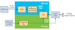
In asynchronous mode, the master clock is provided by a separate clock source locally (Fig. 5). This mode allows for clocks to be as clean as development time and production cost can allow for the system. The system has two independent clocking domains in this case. The PSoC family of devices allows for independent clocking domains within the chip and provides the flexibility of clocking the UDBs completely asynchronous to the CPU and system clocks.
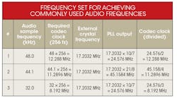
We also encounter the problem of multiple audio rate support. With some clever crystal selection and the use of an integrated PLL, it’s possible to arrive on a frequency set to achieve commonly used audio frequencies. The magic number is 17.2032 MHz (see table).
The asynchronous approach using a PLL provides low-jitter clocks with no locking or synchronization issues. However, using this mode adds another level of complexity to the buffer-management aspects of the system. That’s because the local crystal oscillator is not necessarily locked on to what the host thinks is 48 kHz. The tiny mismatches in frequencies will eventually lead to an over/underflow, causing audible pops if left alone.
To account for this, the USB class provides a feedback endpoint that can be used to adjust the host data rate in order to match the data rates between the input packet rate and I2S output dataflow. The system counts the number of packets sent out by I2S, compares it with the USB start of frame, and adjusts the value of the feedback endpoint to match the average data flow. In simpler terms, the host shrinks or enlarges the number of data samples so that the average over a period of time matches the audio sampling rate. A demonstration of asynchronous-mode USB audio is implemented in the CY8CKIT-046 kit.

About the Author
Sree Harsha Angara
Applications Engineer
Sree Harsha Angara works as an Applications Engineer at Cypress Semiconductor Corp., where he is involved in a wide variety of Embedded system designs using the PSoC platform. He holds a Master’s in electrical engineering from the Birla Institute of Technology and Science, Pilani. His research interests include control theory and embedded applications in power, as well as digital filter theory.
Kendall Castor-Perry
Senior MTS Architect, Programmable Systems Division
For nearly four decades, Kendall Castor-Perry has been chasing signals through electronic systems, wringing out the information they are hiding. He’s a world-class authority on filters and precision analog circuit engineering and a tireless champion of the needs of the customer. He has been widely published and syndicated, especially when sharing his extensive filtering knowledge as “The Filter Wizard.” He holds a BA in Physics from Oxford and an MBA in MBA stuff from London Business School. Kendall is currently Senior MTS Architect in Cypress Semiconductor’s Programmable Systems Division, pushing on the performance:power:price boundaries constraining tomorrow’s critical sensor-processing systems.
Comment About the Article
To join the conversation, and become an exclusive member of Electronic Design, create an account today!

Leaders relevant to this article: