Electrical safety (Hipot) tester functions and application
Electrical safety testers—often referred to as “hipot” testers—are an integral part of electrical and electronic equipment manufacturing. Hipot testers get their name from the high-potential (high voltage) they produce to perform dielectric withstand and insulation resistance tests. In addition to these tests, many hipot testers provide accurate low-resistance measurements and low-resistance/high-current outputs to test ground resistance and ground bond integrity. Modern hipot testers utilize electronic source technology to assure compliance with IEC-61010 that explicitly requires that “the voltage test equipment shall be able to maintain the required voltage for the specified period of time.”
Product safety certification
Manufacturers must submit samples of their products to recognized certification agencies. Nationally Recognized Certification Laboratories (NRTLs) include UL, VDE, FM, ETL, and others. The agency certification process is conducted to confirm compliance with the relevant standard(s). This compliance evaluation investigates two key areas:
- Construction: Mechanical construction, spacing, clearances, etc.
- Safety: To assure safe operation (even under high-stress conditions)
Production electric safety testing functions
Electrical safety testing is an important final step in the production process for most electrical and electronic equipment. Once in production, products must be 100% tested to confirm compliance with the related agency certifications and safety standards. Periodic inspection and calibration of test equipment is a standard requirement to maintain NRTL certification.
Dielectric withstand—hipot
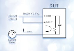
Both AC and DC hipot tests are possible and, in general, the test should use the same type of voltage as it would be during normal operation. However, if a DC hipot test is used on an AC circuit, the hipot voltage should be two times the peak (2 x 1.4 x RMS) + 1000V.
Desirable dielectric withstand test features
- Adjustable maximum output voltage:
- 5KV is adequate for many applications
- Higher voltages (up to 30KV) may be required
- AC and DC outputs
- Excellent regulation—both line and load
- Controllable ramp rates, dwell times, and discharge features
- Phase angle measurement of leakage current—capacitive coupling detection
- Some standards allow for in-phase and quadrature current to be measured separately
- Leakage current due to capacitive coupling may not be a safety concern
- Min/max pass/fail current limits
- Separate limits during ramp
- Programmable multichannel testing
Insulation resistance
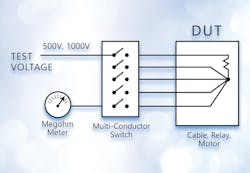
In many instances, insulation resistance needs to be measured between several conductors. Examples include cable/connector assemblies, multiconductor cables and relays. To make this measurement, all the conductors except one are shorted together and the test voltage is applied from the remaining conductor across the bundled ones. Each wire is then, in turn, tested in this fashion (Figure 2).
Desirable insulation resistance test features
- Wide range of selectable test voltages
- Accurate/repeatable high-resistance measurement
- Programmable high-voltage switching accessory
- Multichannel programmable testing
- Pass on steady and Increasing voltage
Ground continuity
Ground continuity testing is performed to confirm that the conductive chassis of a device is safely connected to the earth ground pin on the power plug. This ensures protection against shock hazards even if the equipment suffers an internal short to the chassis. Ground continuity is performed by measuring by applying a low current (e.g., 50 mA) and calculating the resistance from the ground pin on the power plug to selected locations on the exposed surfaces of the DUT. Desirable ground continuity features include:
- Accurate, repeatable low resistance meter
- Plug adaptor accessory to speed testing
Ground bond
Where ground continuity measures the resistance of the safety ground connection, the ground bond test assures the integrity of the connection. Using the same test setup, a high current is passed through the circuit. If the ground bond is solid, the current passes without a change in resistance. If weak, the resistive heating of the current would induce a failure of the bond.
Desirable ground bond test features
- Accurate high current source
- Programmable test currents and test times
- Plug adaptor accessory to speed testing
- 4-wire milliohm meter—providing a Kelvin connection for highly accurate low resistance measurements.
Hipot test station setup and operation
Because there is no substitute for operator competence, the importance of having trained personnel as the first step to a safe testing environment can’t be overstated. Operators must understand the workings and importance of safety interlocks and why the interlocks should never be disabled. They must also understand the hazards of wearing metallic jewelry around electrical equipment and show how to interrupt power quickly in emergency situations.
On a regular basis, typically at the start of every shift, the tester itself should be checked by connecting the tester to both PASS and FAIL samples. These samples should be designed to confirm the proper operation of the tester based on the type(s) of tests to be conducted (hipot, insulation resistance, ground resistance, and ground bond).
Location of the hipot test station
The test area should be isolated from the factory assembly area. It should be located away from foot traffic to assure the safety of passersby and, of course, the safety of the station operator. The area should be conspicuously marked with internationally approved signage, such as "DANGER—HIGH VOLTAGE." During testing, the hipot tester itself should have indicator lights to denote when high voltage is present.
The work area and bench surface should consist of nonmetallic materials; which means that metal work surfaces should be avoided, and no metal objects should not be placed between operator and DUT. All other metal objects should be grounded or be out of the test area altogether. An ESD mat is not a recommended platform for your test station, as it may cause erroneous readings for leakage and is unnecessary in this application.
In addition, the test equipment should provide for immediate and safe removal of the output voltage using internal discharge circuity at the conclusion of the test or if the test is interrupted. Never remove power for the hipot tester. If there is a power interruption, use extreme care in any contact with the DUT. The safest approach is to leave the DUT connected to the hipot tester until power is restored and the tester can conduct its discharge function.
Operator safety considerations
The test station should have sufficient space for the tester and the DUT without the operator having to reach over the DUT to access the tester. There are many safety features that can be added to the test station to prevent the operator from encountering high voltage, such as guards or enclosures. When placed around a DUT they should be nonconducting and be equipped with safety interlocks that interrupt all high voltages when open.
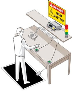
Palm switches can be utilized to prevent the operator from encountering high voltage during testing. The basic operation of a palm switch requires the operator to use both hands to initiate a test with, potentially, a foot switch to activate the test. If one or both hands are removed from the while testing, the test is immediately stopped. No high voltage can be applied to the output terminals and DUT until both switches are pressed simultaneously. The palm switches are connected to the digital I/O on the hipot tester. When the switches are in the down position the start is enabled. Once one switch goes up the safety interlock is enabled, terminating the output voltage of the hipot test. This method is safe, quick, and effective.
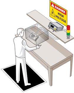
Figure 3 illustrates two alternative approaches to the setup of a benchtop hipot test. In Figure 3a, the DUT is placed on the test bench and a combination of palm switches and a foot switch ensure that the operator cannot make contact with the DUT while the test is underway. The operator is wearing safety glasses. As a practical matter, the use of palm switches is typically restricted to short-duration tests done on a repetitive basis with a series of DUTs. If this test setup is used for longer tests, operators will find a way to defeat the palm switches.
In figure 3b, the DUT is placed under a protective cover with interlock to isolate the operator during the test. The use of an enclosure is a more reliable means to assuring operator safety, particularly when testing requires longer time periods.
More elaborate test stations can include a light curtain interlock, which is an infrared light beam that will open the interlock if anyone interrupts any part of the beam.
Conclusion
Chad Clark is a director of business development at Poway, CA-based Vitrek. He has been with the company for more than 10 years.
This article is derived from a White Paper entitled, “Fundamentals of Electrical Safety Testing” available for download at http://vitrek.com/library/WP1118.pdf


