Boost Time Synchronization Accuracy with the PCIe PTM Protocol

This article is part of the TechXchange: Oscillations, Timing, and Synchronization.
Members can download this article in PDF format.
What you’ll learn
- The need for more accurate time synchronization within a distributed system.
- The challenges of using synchronized time provided by the Precision Time Protocol (PTP) in application software and the solution provided by the PTM protocol.
- An overview of the PTM protocol and the requirements to implement support for PTM in PCIe root ports, PCIe endpoints, and switches.
The PCI Express (PCIe) Precision Time Measurement (PTM) protocol significantly improves the accuracy of synchronized time available to application software. PTM requires hardware support that’s increasingly available in PCIe root port and endpoint implementations. Hardware support is also required in PCIe switches. We believe it’s important to enable the ecosystem with a rich set of devices that can move the industry to the next level of time-sensitive distributed applications.
This article starts by discussing the need for more accurate time synchronization within a distributed system, the challenges of using synchronized time provided by the Precision Time Protocol (PTP) in application software, and the solution provided by the PTM protocol.
It follows with an overview of the protocol and the requirements to implement support for PTM in PCIe root ports, PCIe endpoints, and switches. The article wraps up with the synchronization requirements of several representative applications that require accurate time synchronization.
Improved Time Synchronization with PTM
Accurate time synchronization is critically important for effective coordination within distributed systems. Effective coordination requires that the nodes of a distributed system agree on the ordering of globally visible events. The simplest method of ordering events uses synchronized clocks to timestamp events. In general, more accurate clock synchronization corresponds to higher performance in distributed systems.
The Network Time Protocol (NTP) was the first widely available method of synchronizing clocks on the network. NTP is able to synchronize clocks within about 1 ms for ideal network conditions of low latency and low bandwidth utilization.
The Precision Time Protocol (PTP) improves on NTP time synchronization by several orders of magnitude. PTP is able synchronize time within 1 µs or better over as many as one hundred hops, and within several nanoseconds over a single hop, irrespective of network load.
To achieve this level of synchronization, PTP uses timestamp hardware that’s integrated into the network interface device to timestamp transmission and reception of specific protocol frames. Timestamps captured in the network device are as much as five orders of magnitude more accurate than the legacy method of timestamping frame transmission and reception in software. Software timestamps are less accurate because they’re subject to variability due to DMA queuing delays and, in some cases, process scheduling latencies.
Challenges with PTP Synchronized Time
Time synchronization, using hardware-generated timestamps, is much more accurate compared to that using software timestamps, but a substantial fraction of that accuracy may be lost when the clock is accessed in application software. This is because synchronization protocols using hardware timestamping synchronize the network device clock.
Accessing that clock in application software usually requires a relatively slow memory-mapped I/O (MMIO) read. Because it’s unknown when the device clock is actually sampled during the read operation, the time value received by application software is inaccurate by up to one half the MMIO read latency. An MMIO read of the network device clock may take several microseconds to complete. This means that the 1-µs accurate PTP clock is practically unusable by application software.
Need for Local Clock Replication
To use PTP time in application software, with minimal loss of accuracy, a clock with low access latency is needed to replicate the network device clock. Most modern CPUs have a low-latency clock available to software. Some examples of low-latency clocks are the Timestamp Counter (TSC) on x86 CPUs and the Generic Timer on Arm-based CPUs.
To create a low-latency copy of the network device clock, a transform must be applied to the unsynchronized CPU clock. The transform is derived from the offset between the network device and CPU clocks.
The offset can’t be measured using only software because it’s subject to the same inaccuracy problems as accessing the network device clock directly. Therefore, a hardware-based method of determining the offset between clocks, within the platform, is required.
Hardware-Based Synchronization Using PTM
For PCIe connected devices, the Precision Time Measurement (PTM) protocol provides a hardware-based method of correlating clocks within the platform. The PTM protocol distributes PTM master time from the PTM root to each PTM-capable endpoint device, supplying a common time reference used to correlate endpoint device clocks. Using the common time reference, any endpoint device clock can be correlated with any other endpoint device clock.
PTM master time is propagated from the upstream device to the downstream device for each PCIe link in the path to the endpoint device. PTM propagates time using protocol-specific Transaction Layer Packets (TLPs) that must be timestamped on transmission and reception. This requires hardware timestamping in every port in the path between the PTM root and the endpoint device, including switch ports.
PTM Protocol
For each link in the path from the PTM root to the endpoint, PTM master time is propagated from the downstream port to the upstream port using a PTM dialog. A simple example of two PTM dialogs is shown in Figure 1.
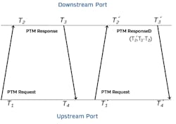
The downstream device initiates a PTM dialog by sending a PTM Request Transaction Layer Packet (TLP). The PTM Request TLP is timestamped on transmit by the upstream port capturing timestamp T1 and on reception by the downstream port capturing timestamp T2. The downstream port responds by sending either a PTM Response or PTM ResponseD TLP.
That response is timestamped on transmit by the downstream port capture timestamp T3 and on reception by the upstream port capturing timestamp T4. The downstream port sends a PTM ResponseD TLP if there’s a valid T2 timestamp from the current PTM dialog and valid T2 and T3 timestamps from the previous dialog; otherwise, a PTM Response is sent.
The PTM ResponseD TLP (Fig. 1, again) contains two PTM data fields: PTM master time and propagation delay. PTM master time is T2 from the current dialog and propagation delay is T3 – T2 from the previous PTM dialog. The relation between the PTM master clock and the downstream device’s clock is computed using the propagation delay and PTM master time fields from the PTM ResponseD TLP, and the T1 and T4 timestamps from the previous PTM dialog. This computation is shown in REF _Ref129198935 \h Equation 1:

The link delay computation assumes that upstream and downstream PCIe link delays are equal, or symmetric. Normally, this is true, but the use of PCIe retimers may introduce link delay asymmetry that is undetectable by PTM. If the link delays are asymmetric, the link delay term used to compute PTM master time must be offset by one half the asymmetry. Any link delay asymmetry introduced by a retimer implementation can only be determined by consulting the retimer documentation.1
Handling Duplicate PTM Messages and Enhanced PTM
If a PTM TLP is retransmitted, there’s a possibility of capturing mismatched transmit and receive timestamps associated with different transmissions. This potentially results in inaccuracies in the link delay and PTM master time computations shown in Equation 1. The PTM protocol makes a best effort attempt to address this issue by using the most recent transmit or receive timestamp.
For instance, if a duplicate PTM TLP is detected by either the upstream or downstream port, the timestamp must reflect the receive time of the most recent TLP. If a downstream port detects a duplicate PTM Request TLP, it’s recommended that the timestamps for the current PTM dialog be invalidated. If a PTM TLP is replayed by either the upstream or downstream port, the timestamp must reflect the transmit time of the last transmitted TLP.
The enhanced PTM (ePTM) capability adds further requirements to improve the accuracy of the link delay and PTM master time computations by invalidating potentially mismatched timestamps.
For example, if an upstream port replays a PTM Request TLP, ePTM requires the timestamps for the current and next PTM dialog be invalidated. If an upstream port detects a duplicate response, it must invalidate its current PTM dialog.
If the downstream port replays a response or detects a duplicate PTM Request TLP, ePTM requires the timestamps from the current PTM dialog be invalidated. In addition, if the downstream port detects a duplicate PTM Request TLP, it must transmit a PTM Response TLP because the T2 timestamp is invalid. Support for ePTM is recommended for all PTM-capable devices and is required for devices that support Flit mode.2
PTM Device Roles and Capabilities
PCIe devices indicate their capabilities using the PTM capability register. The fundamental PTM capabilities are the requester and responder roles. The requester role operates on the upstream port and obtains time from the downstream port on the link. PTM-capable endpoint devices are requesters only.
The responder role operates on the downstream port and provides PTM master time to the upstream port on the link. PTM-capable switches and root complexes are responders on all downstream ports. PTM-capable switches must also be requesters on upstream ports.
Support for ePTM is indicated with the ePTM flag in the capability register. For devices that support Flit mode, this flag must always be set.
Responders that can be a source of PTM master time indicate that using the PTM root capability flag. A PTM-capable root complex is always PTM-root-capable. Switches that are PTM-root-capable can also be a source of PTM master time using their internal clock.2
PTM Enumeration and Device Configuration
PTM-capable devices are configured using the PTM control register. PTM behavior is controlled by two bits that enable PTM and configure a device as PTM root. For each PTM-capable endpoint device, the farthest upstream device, on a path where each device is PTM-capable, should be enabled and configured as a PTM root. PTM must also be enabled on the endpoint and any devices in the upstream path to the PTM root.
Multiple PTM roots may be configured if PTM isn’t supported by the root complex. In this case, PTM master time isn’t guaranteed to be synchronized. Clocks on endpoint devices that are downstream from unsynchronized PTM root devices can’t be correlated.
The effective granularity field of the control register reports the accuracy of PTM master time propagated from the PTM root. It’s primarily used by application software to determine synchronization accuracy on the endpoint device.
Each device reports its clock granularity in the PTM capability register indicating the period of the timestamp clock. The effective clock granularity is configured during enumeration to report the largest clock granularity in the upstream path to, and including, the PTM root device.3
Time Propagation in PTM-Capable Switches
If a PTM-capable switch is configured as PTM root, it’s a responder only on its downstream ports and the PTM protocol is not active on the upstream port. The responder role is described in the “PTM Device Roles and Capabilities” section.
If a switch isn’t configured as PTM root, it propagates PTM master time from the upstream port to the downstream ports. PTM master time is propagated through a switch by setting the switch clock, used for timestamping on the downstream port, to PTM master time obtained on the upstream port.
Specifically, when a PTM ResponseD TLP is received on the upstream port, the switch clock is set to PTM Master Time – link delay + (T4 − T1) accounting for any delay to set the clock. The PTM master time comes from the PTM ResponseD TLP and the link delay computation is shown in Equation 1.
Because the switch clock may drift from the PTM master clock due to differences in the oscillators driving those clocks, the switch must invalidate its clock after 10 ms. If the switch can guarantee, in an implementation-specific way, that the PTM root device and switch are phase locked, with zero drift, the switch doesn’t need to invalidate its clock.4
Applications Requiring Accurate Time
Industrial Automation
Industrial automation is an example of a broader class of cyber-physical systems (CPS) applications where network-distributed synchronized sensors and actuators require accurate time synchronization with bounded network latency. Motor control for a high speed “web fed” printing press is a real-world industrial-automation application requiring accurate time synchronization.
For example, time-synchronization accuracy of 500 ns or better is required in control software. That’s assuming three or more colors are printed separately with less than 0.1-mm alignment, the paper moves at a rate of 10 meters per second, and 5% of the positioning error budget is allotted to time synchronization.5
Distributed Databases
Distributed databases offer better performance, availability, and data integrity, compared to a single-node database, but they rely on accurate time synchronization to globally order transactions. The timestamp accuracy must be sufficient to uniquely identify each transaction. In general, more accurate time synchronization supports a higher transaction rate.
Google’s Spanner database is an example of a distributed database that uses accurate time synchronization to serialize transactions. Event timestamps are provided with a time range (Tmin, Tmax), derived from the clock uncertainty, ensuring the event occurred after Tmin and before Tmax.
To guarantee consistency, the transaction can’t be committed until the current time in the range (tmin, tmax) is certain to be after the transaction time, i.e., the transaction is committed if Tmax < tmin. The greater the timestamp uncertainty, the greater the transaction commit latency and the lower the transaction rate.
Google’s next-generation time-synchronization service, Sundial, provides sub-microsecond time synchronization. CockroachDB is another distributed database that uses timestamps with an uncertainty bound to guarantee consistency.6,7
Financial trading is an example of an application that uses a distributed ledger. To ensure that trading orders are executed in the sequence they’re received, it’s important that they’re timestamped accurately.
United States stock markets require the use of National Institute of Standards and Technology (NIST) disciplined clocks (NISTDC) for timestamping financial trade orders. Stock markets in the European Union must reference one of over 80 international atomic clocks that contribute to Coordinated Universal Time (UTC), one of which is the NIST atomic clock.
While manual orders in the U.S. and EU require timestamped accuracy of one second, automatic or high-frequency trades in the U.S. and EU require timestamped accuracy of 50 ms and 100 µs, respectively. Trades that cross multiple jurisdictions must comply with the most stringent time synchronization requirement. This effectively requires timestamps everywhere that are accurate within 100 µs with respect to an international clock.8
Broadband Cellular Networks
3G and 4G wireless communication standards (Fig. 2) require ±1.5-µs timing accuracy at every radio tower antenna per the requirements of the International Telecommunication Union (ITU) G.8271 specification. 5G wireless communication networks add multiple-input, multiple-output (MIMO) transmission capabilities, enabling multiple 5G towers to cooperatively support improved directionality of reception and transmission, and reuse of scarce RF spectrum.
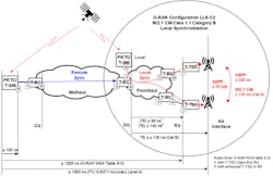
In addition to 3G/4G synchronization requirements, network distributed MIMO requires end-to-end synchronization within 260 ns and clock syntonization within 100 parts per billion (ppb) or better.9
Power-Grid Monitoring
The International Electrotechnical Commission (IEC) Power Utility Profile, IEC 61850-9-3, requires the use of a Full Timing Support (FTS) network. The PTP grandmaster must be accurate to 250 ns or better and each transparent clock, up to a maximum of 15, must be accurate within 50 ns, resulting in end-to-end synchronization of 1 µs or better. This is accurate enough to record the phase of a 60-Hz power signal to within 0.02 degrees for optimal efficiency.
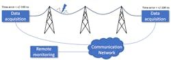
Traveling-wave fault detection requires even better accuracy. As shown in Figure 3, the timestamped disturbance data recorded by two separate monitoring units identifies the transmission-line segment and location of a fault. Since the electrical fault signal travels at nearly the speed of light on open conductors, having timestamp accuracy of 200 ns or better makes it possible to locate the fault within about 60 meters.10
Read more articles in the TechXchange: Oscillations, Timing, and Synchronization.
References
1. Peripheral Component Interconnect Special Interest Group (PCI-SIG), “PCI Express Base Specification Revision 6.0.1,” August 29, 2022. Section 6.21.2.
2. Peripheral Component Interconnect Special Interest Group (PCI-SIG), “PCI Express Base Specification Revision 6.0.1,” August 29, 2022. Section 6.21.3.1-6.21.3.2.
3. Peripheral Component Interconnect Special Interest Group (PCI-SIG), “PCI Express Base Specification Revision 6.0.1,” August 29, 2022. Section 7.9.15.
4. Peripheral Component Interconnect Special Interest Group (PCI-SIG), “PCI Express Base Specification Revision 6.0.1,” August 29, 2022. Section 6.21.3.3.
5. J. Reeder et al., "Single Chip Connected Multi-Axis Servo Drive for Industrial Systems," 2022 IEEE International Conference on Consumer Electronics (ICCE), 2022, pp. 1-4.
6. James C Corbett, et al., “Spanner: Google’s Globally-Distributed Database,” Usenix, November 2020.
7. Yuliang Li, et al., “Sundial: Fault-tolerant Clock Synchronization for Datacenters,” Usenix, October 2012.
8. Michael A. Lombardi, “Synchronizing Stock Market Clocks to UTC(NIST),” XXXIII General Assembly and Scientific Symposium (GASS) of the International Union of Radio Science, August 2020 Presentation, retrieved April, 2022.
9. O-RAN Alliance, “ORAN-WG4.CUS.0-v02.00 Control, User and Synchronization Plane Specification,” 2019, Table 9-1: LTE features with time alignment error requirement at the air interface.
10. IEC/IEEE “61850-9-3-2016: Communication networks and systems for power utility automation - Part 9-3: Precision time protocol profile for power utility automation,” 2016.
Thomas P Heavner et al., “First Accuracy Evaluation of NIST-F2”, 2014 Metrologia 51 174.
“Trimble Navigation,” RES720 Datasheet, retrieved May 2022.
Joseph E Stubbs, PE, “Accurate Synchronization of EtherCAT Systems Using Distributed Clocks,” EtherCAT Technology Group, December 2010 Presentation, slide 23.
J. Lázaro, et al., “Time Sensitive Networking Protocol Implementation for Linux End Equipment,” Technologies 10, no. 3: 55, April 2022.
NYSE, “Pillar Gateway Binary Protocol Specification, Version 4.9, Protocol Version 1.1”, February 17, 2022.
Consolidated Tape Association website, https://www.ctaplan.com/index, retrieved 1-Jun-2022.
UTP website, https://www.utpplan.com, retrieved 1-Jun-2022.
About the Author
Christopher Hall
System Software Architect, Intel
Comment About the Article
To join the conversation, and become an exclusive member of Electronic Design, create an account today!

Leaders relevant to this article: