What's the Difference Between the I2C and I3C Bus?
Members can download this article in PDF format.
What you’ll learn:
- The fundamentals of the Inter-Integrated Circuit (I2C) interface, and its associated protocol.
- What made this simple, robust, chip-to-chip interface so useful for embedded system applications?
- How the evolution of embedded systems led to the development of the Improved Inter-Integrated Circuit (I3C) with its enhanced performance and features.
- How the I3C spec maintains interoperability and backwards compatibility with I2C devices.
The I2C and I3C interconnect technologies are close cousins, both conceived as interfaces for short-haul (intra-board) communication between integrated circuits and other digital devices. As we shall see, I3C is an "improved" version of I2C, which shares a lot of common technology and characteristics that were the result of I2C's somewhat turbulent development history (Fig. 1).
Shortly After the Rocks Cooled…
The Inter-Integrated Circuit (often referred to as I2C, I2C, or IIC) bus's origins date back to the late 1970s and early 1980s during the rapid rise of what would eventually be referred to as "embedded systems."1 Thanks to the increasing complexity and speed of microcontrollers (MCUs) and their associated peripherals, these low-cost single-board computing elements integrated processing, sensing, and control functions that became the basic building blocks for everything from automotive and medical equipment to consumer electronics.
One of the challenges faced by these early developers was finding an efficient way to enable the board's CPU to configure, control, and communicate with the board's analog and digital peripheral devices. It quickly became apparent that connecting these peripherals using the parallel buses commonly found in traditional computing systems were too bulky, expensive, and power-hungry for many of these applications. There were few other options, aside from slow and ungainly UART/USART (universal asynchronous receiver-transmitter/universal synchronous and asynchronous receiver-transmitter) interfaces.
To address this challenge, Philips Semiconductors introduced the I2C interface in 1982, a synchronous, multi-controller/multi-target, single-ended, serial (two-pin) communication bus. During that time, other bus technologies emerged, such as the Serial Peripheral Interface (SPI), but they required more pins and signals to connect multiple devices. Thanks to its robust characteristics, low power operation, and minimal real-estate requirements (silicon and PCB), I2C became extremely popular within the embedded community.
I2C might have enjoyed even greater early success had Philips not engaged in its all-too frequent practice of preventing anyone else from adopting its technologies. This standoff ended in the mid-1990s when several competing IC makers, such as Intersil, Motorola, NEC, Nordic Semiconductor, Siemens, STMicroelectronics, and Texas Instruments found technical/legal workarounds that allowed them to offer products with I2C-compatible interfaces.1
But I'm getting ahead of myself. Let's look at what makes I2C tick.
An Overview of I2C
At the PHY layer, I2C is based on a single transistor, configured with an open-drain/open-collector that can either pull the bus down to a voltage (ground, in most cases), or "release" the bus and let it be pulled up by a pull-up resistor (Fig. 2). By attaching an input buffer to the same line, a single data line can support bidirectional data flow.2
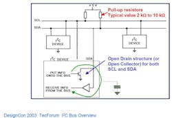
Since no device may force a high on a line, the bus can never experience a short (power rail to ground) if one device tries to transmit a high while another transmits a low. This ability to tolerate bus conflicts allows I2C to support multiple controller devices on the same bus.
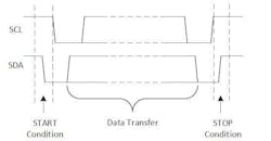
An I2C interface consists of two of these circuits, which serve as the serial clock (SCL) and serial data (SDA) lines. As noted earlier, both SDA and SCL lines must be connected to VCC through a pull-up resistor. A bus is considered idle if both SDA and SCL lines are high after a STOP condition (Fig. 3).
The I2C reference design has a 7-bit address space that can be expanded with an infrequently used 10-bit extension. The most common I2C bus speeds are the 100-kb/s standard mode and the 400-kb/s fast mode.
Later revisions of I2C can host more nodes and support faster speeds that include 400 kb/s (fast mode), 1 Mb/s (fast mode plus), 3.4 Mb/s (high-speed mode), and 5 Mb/s (ultra-fast mode). For applications that require even higher resistance to interference and line impairments, there’s also a 10-kb/s (low-speed) mode. In addition, I2C can support arbitrary low-speed clock frequencies.3
Each I2C bus system includes a controller device, (formerly referred to as a "master"), and one or more target devices (formerly referred to as "slaves"). Target devices can’t transmit data unless they’re addressed by the controller. Every device on the I2C bus has a specific device address. This allows each device to be individually configured and controlled by the controller, which can read or write to any of the device's internal registers.
Communication between controller and target devices is performed using the following steps:
Transmit (Controller-to-Target):
- The controller-transmitter sends a START condition and addresses the target-receiver.
- The controller-transmitter sends data to target-receiver.
- The controller-transmitter terminates the transfer with a STOP condition.
Receive (Target to Controller):
- The controller-receiver issues a START condition and addresses the target-transmitter.
- The controller-receiver sends the requested register to read to target-transmitter.
- The controller-receiver receives data from the target-transmitter.
- The controller-receiver terminates the transfer with a STOP condition.
I2C devices transmit data in eight bit packets (one bit per SCL pulse), each one followed by a one-bit Acknowledge (ACK)/Not Acknowledge (NACK) handshake bit sent by the receiving device to signal that the exchange is successfully completed (or not).
If two I2C controller devices attempt to use the bus at the same time, a collision-detection mechanism senses the conflict and invokes an arbitration sequence that determines which device gets to "speak" first. (Additional details about these, and other aspects of the I2C's electrical and logical characteristics, can be found in a pair of excellent application notes by Texas Instruments2 and NXP Semiconductor.3)
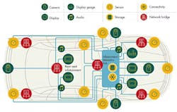
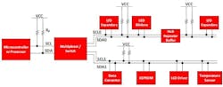
This simple bus architecture enables an MCU or a more powerful microprocessor to access a large number of peripherals using very little power and board space (Fig. 4), factors that have made it a dominant interconnect technology for embedded systems.
I2C's Limitations
Despite its many advantages, I2C began to show its age and has had increasing difficulty addressing the requirements of modern advanced embedded applications. For example, I2C's transfer speed limits, caused by relatively slow rise time of its open collector interface, become choke points in next-gen automotive applications as the data generated by cameras, LiDAR, and other safety-critical sensors exceed even I2C's fastest transfer speeds.
In addition, it had very few advanced features, such as in-band interrupts, a standardized set of common command codes, recovery, and dynamic address assignment that can be very valuable for managing intelligent peripheral devices.
Enter I3C
To address these and other issues, the Improved Inter-Integrated Circuit standard (usually referred to as I3C or I3C) was developed as a collaborative effort between electronics- and computer-related companies under auspices of the Mobile Industry Processor Interface Alliance (MIPI Alliance), and released to the public in late 2017.
At the PHY level, I3C uses a dual-mode interface based on high-speed push-pull outputs that enable much higher transfer rates, but it can also be configured to be compatible with an I2C device's slower open-drain outputs.
In transactions involving I2C target devices, the SCL clock signal generally has a duty cycle of approximately 50%, but when communicating with known I3C targets, the bus controller may switch to a higher frequency and/or alter the duty cycle (Fig. 5). To simplify implementation, the standard includes extensions to the communication protocol that make it easy to determine which mode to use.
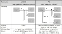
IC3's push-pull interface supports a standard-data-rate (SDR) mode with a throughput of between 10 and 12.5 Mb/s, plus a high-data-rate (HDR) mode that uses double-data-rate (DDR) signaling to achieve a 25-Mb/s raw data rate (20 Mb/s effective). The I3C standard also includes a provision for multi-lane operation, which can expand a channel's capacity by up to 4X.
Equally important, I3C incorporates many functions and features needed to support advanced embedded systems. This includes:
- Support for in-band interrupts (over the serial bus) that eliminates the need for separate pins.
- A standardized set of common command codes for special operations (which can be invoked by writing them to the reserved address 0x7E) and support for a command queue.
- Dynamic address assignment (DAA) for I3C targets, while still supporting static addresses for I²C legacy devices.
- Error detection and recovery (parity check in SDR mode and 5-bit CRC for HDR modes).
An updated version of the standard, issued in December of 2019, added several additional features, including support for multi-controller operation and a well-defined protocol for hand-off between controllers.
An excellent summary of the I3C interface and its full feature set can be found in “I3C Application Note: General Topics,” published by the MIPI Alliance.4
A "Mostly Open" Standard
IC3 is an open standard insofar as anyone can use it. However, access to the full specification, and the rights to use it commercially, requires a paid membership in the MIPI Alliance.
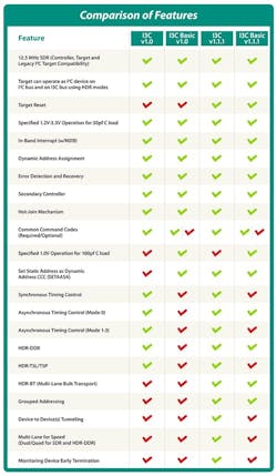
The good news is that there’s a royalty-free subset of the standard, known as MIPI I3C Basic, available to non-member organizations under a RAND-Z license. The basic version includes many of the advanced features available in I3C 1.0 (Fig. 6), but it lacks some of the potentially more difficult-to-implement ones such as the optional HDR modes like DDR.5
References
1. “I2C,” Wikipedia.
2. “Understanding the I2C bus,” Jonathan Valdez, Jared Becker, Texas Instruments, June 2015.
3. “I2C-bus Specification and User Manual,” NXP, October 2021.
4. “I3C Application Note: General Topics,” MIPI Alliance Inc., 2022.
5. “I3C (Bus),” Wikipedia.
About the Author

Lee Goldberg
Contributing Editor
Lee Goldberg is a self-identified “Recovering Engineer,” Maker/Hacker, Green-Tech Maven, Aviator, Gadfly, and Geek Dad. He spent the first 18 years of his career helping design microprocessors, embedded systems, renewable energy applications, and the occasional interplanetary spacecraft. After trading his ‘scope and soldering iron for a keyboard and a second career as a tech journalist, he’s spent the next two decades at several print and online engineering publications.
Lee’s current focus is power electronics, especially the technologies involved with energy efficiency, energy management, and renewable energy. This dovetails with his coverage of sustainable technologies and various environmental and social issues within the engineering community that he began in 1996. Lee also covers 3D printers, open-source hardware, and other Maker/Hacker technologies.
Lee holds a BSEE in Electrical Engineering from Thomas Edison College, and participated in a colloquium on technology, society, and the environment at Goddard College’s Institute for Social Ecology. His book, “Green Electronics/Green Bottom Line - A Commonsense Guide To Environmentally Responsible Engineering and Management,” was published by Newnes Press.
Lee, his wife Catherine, and his daughter Anwyn currently reside in the outskirts of Princeton N.J., where they masquerade as a typical suburban family.
Lee also writes the regular PowerBites series.
Comment About the Article
To join the conversation, and become an exclusive member of Electronic Design, create an account today!

Leaders relevant to this article: