HSIO Connector Plus High-Speed Twisted Pair Meets Next-Gen Video/Data Needs
This file type includes high resolution graphics and schematics when applicable.
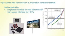
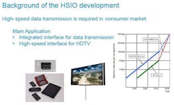
World demand for gaming/entertainment systems continues unabated, with forecasts showing annually rising growth rates. Next-generation televisions (UHDTV, more commonly known as 4K by consumers) keep on pushing video-signal delivery well beyond traditional high-definition multimedia interface (HDMI) and high-definition (HD) rates. Emerging 4K TV technology virtually doubles previous HD resolution rates (Fig. 1).
In enterprise markets, the “Internet of Things” trend continues to the main driver with cloud, streaming and server/storage-related solutions.
Typical trends align with those of other computing and electronic devices—shrinking form factors coupled with demands for increased bandwidth and performance. New applications discussed in this article fulfill these high-speed video/data requirements by merging versatile high-speed I/O (HSIO) interconnects with high-speed, twisted-pair cable technology.
The Problem
As devices become smaller and thinner while demanding more bandwidth, the main dilemma is how to accommodate larger-form-factor, high-speed input modules (e.g., high-end graphics generators) within the ever-shrinking available space of output devices. Not only do these platforms need more compact solutions, but they also require methods for maintaining a robust and reliable interconnect and meeting a wide range of performance requirements, intuitive end-user access, and versatile adaptations—all within a cost-effective model.
The main objective is to merge an output device incorporating a high-speed cable with a high-speed input device. The larger input device can then be placed in a more remote location from the output device. This input device may sometimes be referred to as a docking device, depending on the specific application (as in a gaming or video device). In an enterprise product, the input device may simply be located remotely from the output device (as in a fixed-size I/O generator and graphics processing unit).
Solutions
The basic set of building blocks for these solutions combine HSIO connector technology with high-speed twisted-pair cable technology. Blending the two creates versatility that excels at meeting multiple requirements.
One example would be for entertainment solution that would employ a cabled connection between a thin LCD device (e.g., TV) and its remote processing unit. This is sometimes referred to as a one cable concept (OCC). Similar examples exist within the gaming industry.
A PCIe generation 3 (Gen 3 data rates of 8 Gbits/s at 85 â¦) solution, offering scaling ability to higher bandwidths for PCIe generation 4 (Gen 4 data rates of 16 Gbits/s), is one good example of a possible solution for an enterprise-type products. Many data rates are supported, such as USB (2, 3, 3.1, etc.), DisplayPort (DP, versions 1.3, 1.4), HDMI, etc. Typical cabled lengths are up to two meters with extended lengths under evaluation between three and four meters.
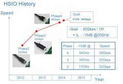
Lab tests have also demonstrated data rates approaching 20+ Gbits/s per lane, with a goal to reach 40 Gbits/s within one year (Fig. 2). In some cases, higher-speed performance may offer simplified silicon solutions at the computing device, and therefore not be restricted to any single data rate. High-speed twisted-pair cables can be tuned for other signal impedance control, such as 85 â¦, 100 â¦, etc.
Some high-speed data solutions may potentially be coupled with power requirements exceeding 200 W/20 V dc. Specific cable-construction methods help maintain low levels of insertion loss and crosstalk. Typical connector contacts are capable of 1.5 A. A variety of widths can be considered for higher amperages, as required.
Analysis/Simulation
Managing multiple signal frequencies and data rates when they’re combined within a common application presents many signal-integrity challenges. Identifying analytical gaps and implementing simulation software for electromagnetic-interference (EMI) and target radio-frequency (RF) simulations further demonstrate the ability to tune this technology, achieving successful solutions across multiple usage models. Versatility and longevity are some of the key attributes for integration capabilities.
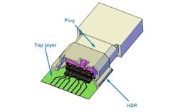
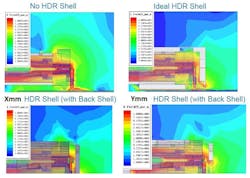
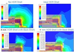
Channel simulation capabilities are commonly performed to help develop optimal designs while minimizing design cycles. Both cable-construction and connector-contact designs are included in simulations and analysis (Fig. 3). Figures 4 and 5 show simulation results in different RF modes.
HSIO Receptacle Technology
Generally, HSIO technology utilizes a single row of surface-mount-technology (SMT) pads and contacts attached at the printed-circuit-board (PCB) end, referred to as the “fixed connection.” It’s typically configured on a 0.4 mm fine pitch. Finer pitches may be possible and are currently being explored.
The mated plug/receptacle interconnect (referred to as the separable connection), which is then configured as a dual-row tongue/slot, typically uses a wider pitch. Plug and receptacle contact and pad pitches are typically 0.5 to 0.6 mm, and designed for repeated alignment and reliable connections. These contact pitches can be tuned for subsequent performance requirements. In some cases, using a wider pitch may help achieve more cost-effective targets while still enabling sufficient design margin, which minimizes the need for design refinements when scaling to next-generation products.
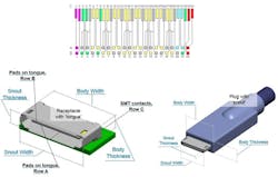
Grounding is a key differentiator with this technology. Differential or single-ended pair grounding can be tailored as needed by combining and “weaving” ground pads within multiple signal pads and contacts. Combining power and ground is subsequently available as needed. Separating pad planes on the plug and receptacle’s mating tongue/slot between opposing rows is an additional key attribute. Figure 6 shows a typical wiring diagram of a HSIO receptacle.
In most cases, these interconnects are capable of meeting 10,000 mate/un-mate mechanical cycles. Electronic Components Industry Association (ECIA, formerly the Electronic Industry Association) industry standards are the typical protocol for product qualifications. Detailed product specifications will report final results accordingly. Gold plating in key areas is typical and can be specified as needed. Higher conductivity contact materials are always available for specific needs as required.
This file type includes high resolution graphics and schematics when applicable.
Meeting the needs of increasing data rates and smaller-device form factors will continue to challenge copper interconnect solutions. Copper-based solutions using these HSIO technologies will continue to be cost-effective solutions into the foreseeable future.
Steve Figuerado, field application engineer for TE Connectivity’s Consumer Devices Division, has more than 25 years of industry experience in product design for system impact printing, mid-range/X86 server computing/storage, and related peripherals. He received his education in mathematics and mechanical engineering at Austin Community College and Broome Community College in Texas and New York State.
