Using Magnetic Cores in Computers
Author
Robert D. Kodis
Head, Research and Development Section, Computer Dept.
Raytheon Manufacturing Co., Waltham, Mass.
MAGNETIC core circuits can be found performing the computer functions of storage, manipulation, control, amplification, regulation, and several minor special applications. This article will attempt to support the growing trend to the use of this two-state component by cost, specification, and circuit analyses. The use of the magnetic core will be discussed in function groups: internal memory; buffer memory or input-output memory; high speed logic; and finally low speed logic circuits.
Internal Memories
The internal memory is usually a major factor in controlling the overall system characteristics. Thus, the memory specifications are important and should include at least: (1) number of registers and their size; (2) mode of operation-parallel, serial or any combination; (3) initial and repeated access time; (4) cost; (5) environmental conditions; (6) operating margins.
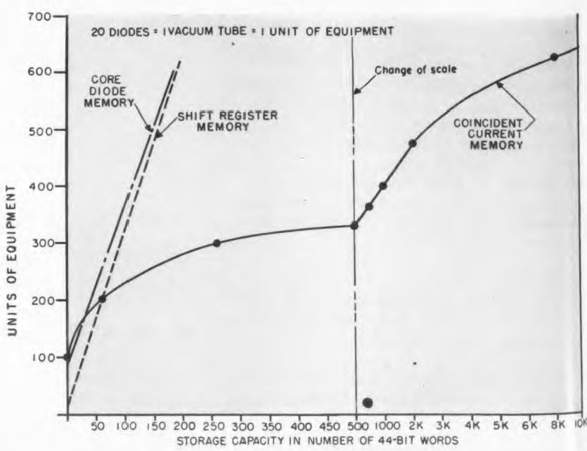
The unwritten requirements for all the core circuits to be discussed include reliability, a combination of operating margins, life, and transient conditions. The reliability of magnetic core circuits has been demonstrated to be mainly dependent upon the equipment and components associated with the core rather than the core itself. Thus, it is the high ratio of cores to other components that provides such high reliability of large coincident current memories. Figure 1 illustrates storage size for 44-bit words versus the amount of equipment for control, drive, selection and other functions considered to be part of the storage system (a unit of equipment is defined as one vacuum tube or twenty diodes). While in these memories, cores are used only in the main storage function, the use of cores in the selection, control, or drive functions would not radically change the comparison shown. In fact, it would improve the reliability of all three memories.
Figure 1 presents a persuasive argument for using coincident current core storage in memories of 4000 bits or more. Consequently, we find the coincident current memory most often used in large, general purpose storage where its great saving in equipment per unit of storage easily offsets its lack of flexibility. On the other hand, we find the shift register memory in small or special purpose systems, where it requires the least equipment. It becomes evident, then, that the combination of these two basic types of storage can provide useful circuits for special requirements, such as a memory using coincident current to write in and shift register techniques to read out.
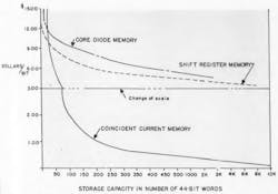
The low cost involved in using coincident current techniques in memories of 35 words (1,500 bits) or more is demonstrated by Figure 2. However, a qualification of this low number is usually required when fitting such a small memory into the system. Such qualifications might be a parallel memory in a serial system, certain decoding of address selection, or the flexibility required of a memory cycle. The additional equipment required usually pushes the dividing line closer to 50 words. The operating margins of coincident current memories lie in an area of 1 to 1.3, whereas shift register memories have margins greater than 1 to 3. Systems with operating margins in excess of 8:1 are available. The core-diode memory has served useful purposes in several systems. At present, however, it does have the disadvantage of a high overhead cost in equipment, as shown by Figure 1, and it is relatively poor in operating margins, life, and reliability due to the operating characteristics of the diodes.
The shift register memory has an initial access time of 0.2-microsec and a repeated access of less than 2 microsec. The coincident current memory has an initial access time of one and a repeated access time of less than 7 microsec.
Buffer Memories
In buffer memories, additional specifications are usually required, such as the ability to operate over a range of pulse rates, accept either parallel or serial information, complement, insert, or shift stored information. The magnetic core shift register is the only component that can accomplish these functions directly. Thus, the shift register is highly practical for use in buffer memories as large as 10,000 bits. Buffers have also been built using core-diode type storage. The experience reported from these equipments showed usable operating margins, but relatively poor reliability and life, due again to the operating characteristics of commercially available diodes.
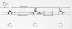
Flexibility of controls makes the shift register the only type of buffer which is usable with certain frequency modulation types of magnetic recording systems. A register is normally used in such manner so that all information is transferred upon command. However, the ability to transfer part of the information any number of times while the remainder is static is very useful in simplifying certain timing problems. The two-core per-bit or Harvard-type5 shift register has almost no system application that is not better implemented by one-core per-bit “Single Line” registers. The principle of the “Single Line” register can best be understood by referring to Figure 3. As may be seen from the illustration, all the magnetic cores are driven from a common shift line. In this application, the read out of the nth core is delayed from writing into the n+1 core for a period greater than the shift pulse duration.
Magnetic shift registers using selenium diodes are still doing useful work after 20,000hr. However, a continual increase in forward resistance of the diode has taken place until the resistance has about doubled at 18,000hr. The designer of long-life registers using selenium diodes must recognize this situation. Magnetic shift registers employing germanium, gold-bonded diodes have had over 8,000hr operation with no measurable changes in their operating characteristics or their output signals.
High Speed Logic
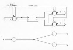
The logic required for control and data manipulation in computing systems can be handled in many cases by magnetic core logical elements. For pulse rates in the megacycle range the core logic must still be considered merely a laboratory device. However, for pulse rates up to 500 kc, the cores should definitely be considered for logical structures. The types of circuits that are being studied for this purpose are too numerous for recounting here.Also, since we are comparing only practical devices, this reduces the discussion to ones now being used in workaday systems. The “Single Line” magnetic core shift register is the basic type of circuit used in the “Single Line” Magnetic Core Logical Element10. Since these are relatively new techniques, a brief description is in order. Figure 5 illustrates a circuit diagram in which one core feeds two others. In theory, this type of branching may be done for any number of cores. The inhibit function can be accomplished by reversing the polarity of the input winding, as shown in Figure 4. At present, the magnetic core logical element should be limited to a combination of three inhibit or input windings. However, more affirmations may be made on one logical stage by buffering the outputs of several elements together on the diode, as shown in Figure 6. As a matter of fact, the output from one element can be used to drive three other stages.
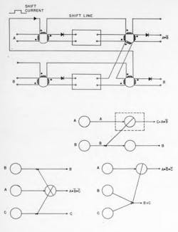
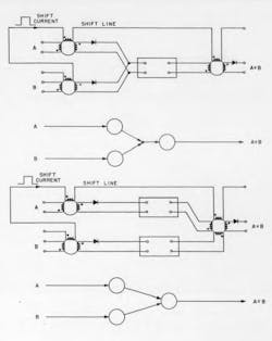
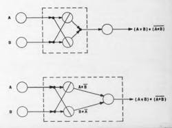
The combination of these circuits permits the accomplishment of any logical function. For example, the “Exclusive Or’’ function is easily constructed with three cores, as shown in Figure 7. The simplicity with which many other functions are implemented suits it for use in moderate and Iow speed systems. For example, a serial arithmetic unit capable of handling 24 digit binary numbers and sign, has actually been built. It uses only 150 magnetic cores, 150 diodes, and 8 vacuum tubes to perform all the manipulative functions, controls, and storage and operates at 0.25 M pulse rates. It requires only 0.25 cubic feet of space, weighs 15 lb., and consumes a mere 130 W, including filament power. A unit of this type would have obvious application to airborne problems where volume, weight, and power requirements are prime considerations. The range of environmental conditions over which this type of component will operate is quite useful even though they are still not all that is desired. For example, good operation can be held over the ambient temperature range from -80°C to +85°C.
The magnetic core logical element is designed to be a low impedance, low ¡lower device. This characteristic enhances the core circuits, but leaves them at too low a voltage level to satisfy the requirements of vacuum tube circuits. The limitations on the usage of a magnetic core logical element still depend upon pulse rate, power level and choice of diodes. (On the other hand transistors work well with this type of magnetic core circuit11.)
Low Speed Logic
In the low speed portion of computing systems the magnetic core logical element may be required to control mechanical equipment. If the logical statements require many cores for their implementation, the low power cores would be used and power amplification provided for the output. However, where the control function is simple a magnetic core of suitable size may be employed to provide the power directly. The cores themselves can be used for power gain to operate thyratrons or relays. Perhaps of even more significance is the direct read in and control of magnetic cores from mechanical and electro-mechanical sources. This elimination of all vacuum tubes and transistors places the reliability problem squarely on the diode. On the other hand, magnetic core-transistor circuits that can perform all of the above logical functions employ no tubes or diodes. Thus, we have a basic choice: diodes with a few tubes versus transistors.
The “Single Line” magnetic core logical element has a reliability close to the “Single Line'’ magnetic shift register. The number of elements driven from one tube depends upon the maximum density of positive information, power level of the driving tube, repetition rate of the information, power level of the cores, and the high-voltage supply used. The range of 16 to 65 cores per driving tube is common. Tube types such as 6AlT5, 5881, and 6293 are being used as drivers. The driver can be considered as a pulsed power supply, since it does not normally enter into the logical structure.
The magnetic core is also being used as a different type of logical element or gate in selection systems. Several laboratories have developed saturable transformers, biased cores, and time-pulse sequence gates. These techniques are useful as driving source for other magnetic circuits, and magnetic recording, writing, and reading selection systems.
The type of equipment required to transfer information from card to tape or tape to printer is especially susceptible to implementation by magnetic core circuits. The shift register storage eases the requirements of reading into storage from card reading brushes or other mechanical contacts. This characteristic is due to the ability to make the read-in to each core independent, and to combine parallel read-in with serial transfer. These equipments may be required to perform the functions of code conversion, speed conversion, radix conversion as well as format controls and checking. These functions, when accomplished by magnetic core logical elements, are best accompanied by shift register type storage.
A simple example is a binary-to-binary coded decimal converter and binary coded decimal to binary. This unit uses 100 cores to convert over 1000 decimal digits per second. The promise of unusual reliability and long life of the magnetic core has been the motivating factor in most of the new developments using this component. The possibility of reduction in cost, weight, and power requirements has its measure of attraction. It is quite safe to predict that most computers designed in 1955 will use more magnetic cores than any other two-state component.
References
1. An Wang, “Static Magnetic Memory—Its Application to Computers and Controlling Systems” Proc. A.C.M., May 2, 3, 1952.
2. I. L. Auerbach, “A Static Magnetic Memory System for the Eniac” Proc. A.C.M., May 2, 3, 1952.
3. W. N. Papian, “A Coincident-Current Magnetic Memory Cell for the Storage of Digital Information” Proc. IRE, Vol. 40, No. 4, April, 1952.
4. J. A. Rajchman, “A Myriabit Magnetic-Core Matrix Memory” Proc. IRE, Vol. 41, No. 10, October, 1953.
5. An Wang and W. D. Woo, “Static Magnetic Storage and Delay Line” Journal of Applied Physics, Vol. 38, June, 1950.
6. S. Ruhman, R. D. Kodis, and W. D. Woo. “Magnetic Shift Register Using One Core Bit”, IRE National Convention, 1953.
7. J. D. Goodell, “Testing Magnetic Decision Elements”, Electronics, January 1953.
8. M. K. Haynes, “Magnetic Cores as Elements of Digital Computing Systems” Technical Report to Office of Naval Research, August 28, 1950.
9. Norman B. Saunders, “Magnetic Binaries in the Logical Design of Information Handling Machines” Proc. A.C.M., May 2, 3, 1952.
10. S. Guterman, R. D. Kodis, and S. Ruhman, “Logical and Control Functions Performed with Magnetic Cores”, Proc. IEEE Vol. 43, No. 3, March, 1955.
11. S. Guterman and W. E. Cary, “A Transistor-Magnetic Core Circuit: A New Device Applied to Digital Computing Techniques”, IRE Convention, 1955.
12. S. Guterman and R. I. Kodis, “Magnetic Core Selection Systems”, IRE Convention, 1954.
13. I C. Minnick, “Magnetic Switching Circuits”, Journal of Applied Physics, April, 1954.
14. I. Moffat, “Saturable Transformers as Gates”, Quarterly Report Second Series fo the Computer Fellowship No. 347, March 1954 — Mellon Institute of Industrial Research.
