Inside a wind turbine simulation
Consider the inside of a typical wind turbine nacelle. It will contain a gearbox, electrical controls, a generator, hub mounting, blade controls, and several other major systems. In the case of today's utility scale turbines, all of this equipment is typically designed by different sets of people.
The process of uniting designs created by different teams often leads to integration issues. Despite this challenge, wind turbine power capacities have risen from about 20 kW in the 1980s to 7.5 MW today by using tools that enable early detection of problems with subsystem integration. These tools include system-level simulation models.
Experts in mechanical, hydraulic, electronic, and controls departments not only use simulation individually but also combine their models to optimize turbines through multidomain system-level testing. More specifically, a technique called Model-Based Design has been shown to halve development time for wind turbines and other complex mechatronic systems.
Model-Based Design addresses problems associated with designing complex controls through a combination of mathematical and visual methods. Model-Based Design proceeds in four, general steps: modeling , refining the design through simulation, automatically generating code for the embedded controller and testing, and continuous testing and validation.
The Model-Based Design approach generally involves having developers define mathematical models using continuous-time and discrete-time building blocks. This has an advantage, particularly in portions of the turbine design that involve writing software, by making it possible to employ hardware-in-the-loop simulation to test dynamic effects quickly and efficiently.
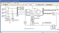
When it comes to the plant-modeling of a wind turbine, the process usually involves creating a block diagram-level description that incorporating differential-algebraic equations governing plant dynamics. This approach is combined with physical modeling where physical networks are assembled from components that represent the physical elements that make up the turbine.
Model-Based Design involves offline simulation and real-time simulation. Engineers typically investigate the time response of the dynamic system model to complex, time-varying inputs. The point is to find gross specifications, requirements, and modeling errors early rather than late in the design effort.
Applying Model-Based Design at this early point in the development process helps engineers build a virtual model of the wind turbine that incorporates its mechanical, electrical, hydraulic, and other physical aspects. Linking the model to the system requirements lets it serve as an executable specification for both subsystems and the system as a whole. This brings an unambiguous understanding of the requirements, which reduces the risk of design errors.
There are several advantages to using Model-Based Design in wind turbine design efforts. As we've noted, simulation identifies multidomain design and integration problems early, when they are easiest to correct. Additionally, it creates a behavioral simulation model through which the design can be tested against requirements concurrently as the design goes through successive iterations. Models can also serve as test benches for implementing components and thereby eliminate the need to create tests by hand. For similar reasons, they reduce interpretation errors. Finally, designers can use simulations to evaluate trade-offs, component interactions, and system-level metrics quickly before committing to expensive hardware prototypes.
Continue on next page
The process of building a system model starts with the desired power output of the turbine, from which engineers can determine the size of the generator. The electrical system is among the more complex parts of the turbine. Much of the complexity is in ensuring the system connects to the grid or collector network in a way that meets requirements for voltage and frequency stability. Other constraints apply in the case of faults on the grid itself, where turbine control systems must keep the turbine's active and reactive power in an acceptable range.
Engineers can model the electrical system as system-level elements representing the inverters, generator, and other components. Alternatively, they can assemble models of the power electronics to build system models from the ground up. It is also increasingly customary to run simulations that extend beyond the individual turbine to include portions of the grid. This sort of modeling lets engineers ensure the generator connects and disconnects without disrupting other systems attached to the grid.
The size and type of generator, of course, impacts modeling decisions. The generator shaft must spin much faster than the turbine blades to generate power. A gearbox, typically a planetary design, generally enables an acceptable range of speed ratios that are identified in the design phase. (Super-large off-shore turbines in the 10 MW range now on the drawing boards incorporate a direct-drive scheme that eliminates the gearbox.)
But simulation could help test other technologies for connecting the rotor to the generator, such as hydrostatic transmissions. Simulation tools provide gear models (simple, planetary gear sets, and so on) that can be combined to create nearly any gearbox design. Tools for simulating hydraulic systems contain elements typically found on a schematic (including cylinders, orifices, and more), so engineers can work directly from the schematic and assemble a working model of the system in a matter of hours. By integrating mechanical, electronic, and hydraulic domains in the early phases of development, engineers can rapidly and inexpensively test new technologies and evaluate their advantages and disadvantages
Often, as with other types of mechanical designs, the physical data for wind turbine components are stored in CAD models. Thus parameters such as mass, inertia, and dimensions can be imported into the system-level simulation model for the blades, nacelle, pitch actuators, yaw gears, and the housing for the geartrain and generator.
It is illustrative to see how simulation can aid in designing a pitch system used in horizontal-axis wind turbines to control the angle of the blades. Blade angle manages the speed of the turbine rotor, and thus maximizes the amount of power that the generator will produce in light winds while helping to prevent overspeed when things get rough. This system primarily consists of either hydraulic or electromechanical linear actuators that turn the blades in the hub. Their design depends upon factors that include the size and weight of blades, the range of motion and speed of response that the actuation system delivers, and what happens when actuator power fails.
As with any mechatronic design, simulation can help identify worst-case scenarios. In pitch controls these include the amount of force or torque that the actuators must provide, and the speed at which the actuators must move. Once designers have identified these requirements, they can simulate different technologies to determine which might be most advantageous. For example, electric motors are efficient but may not be powerful enough to move and hold the blades. Hydraulics may be less efficient but are powerful and will hold their position during a power failure. What-if scenarios during simulation can help evaluate such options.
Similarly, active yaw systems that point turbines into the wind are candidates for simulation. These typically position the nacelle on either a roller or gliding bearing and rotate it using either hydraulic or electric motors.
As the weight and dimensions of the nacelle and rotors are defined, designers can use generic models of the yaw actuators to determine the amount of torque needed to point the turbine into the wind. With those requirements refined, designers can simulate with motors from specific suppliers. Simulation tools provide generic motor models parameterized so engineers can easily update the model with the values directly from manufacturer data sheets. Simulation runs can determine how the system will behave and answer such questions as whether gear backlash will be a problem with nacelle positioning, or whether motors can overcome the friction in the bearing to smoothly rotate the turbine without overshoot.
Continue on next page
Both the pitch and the yaw actuation systems, of course, have associated control systems. One reason many organizations create these control models, plus all other models associated with the wind turbine, in a single environment is to create an accurate model of the overall turbine, i.e. a plant model.
Virtual integration and test
At the start of the development process, engineers create a system-level model to determine the requirements for each subsystem. They then flesh-in the details as they design and model the individual subsystems. Ultimately, these individual subsystem models should be integrated into the overall system model and simulated in one environment. The idea is to let engineers identify integration errors before prototypes are built.
In addition, the process of integrating the subsystem models is a critical step in the development of a supervisory control system for the turbine. Wind turbines operate in disparate environments and under a wide range of conditions. To provide assurances that the turbine performs as expected some virtual tests will include all subsystems, and for each test the level of detail required in each subsystem may change. Model developers may need to provide models of their subsystem at different levels of fidelity so that tests that involve the entire turbine can be run efficiently.
Model developers must keep in mind that the models they devise will also be used for tasks other than desktop simulation. For example, engineers can define control algorithms as flow charts in the model, then have the logic automatically convert to production code that downloads directly onto embedded controller hardware. In this process, engineers will typically add additional details to the algorithm that are required by the embedded controller, such as data precision and range of values.
Turbine designers can use the models of the physical systems for hardware-in-the-loop testing, executing the simulations on special-purpose real-time computer systems. To make this kind of testing possible, engineers modeling the physical system must capture the relevant dynamics without resulting in simulations that consume too much computation time. With a single environment that supports modeling at different levels of fidelity, engineers can balance this trade-off and produce models that can be reused throughout the development process.
It is unlikely that the controller will work on the actual system as well as it did in simulation. Thus there is usually an iterative debugging process that analyzes results on the actual target and updates the controller model. Model-Based Design tools allow all these iterative steps to take place in a unified visual environment.
Resources
The MathWorks Inc., www.mathworks.com MathWorks webinar on wind turbine simulation, www.mathworks.com/programs/cd_physical/
About the Author
Comment About the Article
To join the conversation, and become an exclusive member of Electronic Design, create an account today!

Leaders relevant to this article: