Low Current, Power Measurements Require Extreme Accuracy

Key considerations for using a low current source include the maximum current, minimum current, and step resolution; the output settling time required; and the level of voltage compliance needed. It must also have a level of noise acceptable for the application and sufficiently high output impedance. If the source’s output impedance is only 100× higher than the resistance of the Device Under Test (DUT), then the actual current through the DUT will be off by 1%.
DC voltage, DC current, and resistance are measured most often with digital multimeters (DMMs). Generally, these instruments are adequate for measurements at signal levels greater than 1μV or 1μA, or less than 1 GW. However, they don’t approach the theoretical limits of sensitivity. For low level signals, more sensitive instruments such as picoammeters must be used.
A number of error sources can impact low current measurement accuracy. For example, the ammeter may cause measurement errors if not connected properly. The ammeter’s voltage burden and input bias current may also affect measurement accuracy. The source resistance of the device under test will affect the noise performance of a feedback ammeter. External sources of error can include leakage current from cables and fixtures, as well as currents generated by triboelectric or piezoelectric effects.
Leakage currents are generated by stray resistance paths between the measurement circuit and nearby voltage sources. Leakage current is an error current that flows (leaks) through insulation resistance when a voltage is applied. It generally becomes an issue when the impedance of the device under test is comparable to that of the insulators in the test circuit. This current can degrade the accuracy of low current measurements considerably. To reduce leakage currents, use good quality insulators, reduce the level of humidity in the test environment, and use guarding. The latter will also reduce the effect of shunt capacitance in the measurement circuit. Guarding is a very effective way to reduce leakage currents. A guard is a low impedance point in the circuit that’s at nearly the same potential as the high impedance lead being guarded.
Humidity may also degrade low current measurements. Different types of insulators will absorb varying amounts of water from the air, so it’s best to choose an insulator on which water vapor doesn’t readily form a continuous film. Sometimes, this is unavoidable if the material being measured absorbs water easily, so it’s best to make the measurements in an environmentally controlled room. In some cases, an insulator may have ionic contaminants, which can generate a spurious current (especially in high humidity).
Elimination of error sources, leakage currents, and environmental effects will aid in the measurement of low currents. Low-level currents are a major concern to the designers and test engineers who are designing IoT products and power conversion devices. Although engineers do not need to read down to pA levels often, they may need to read down to nA levels to qualify and evaluate new low power components.
For example, IoT products are typically battery-operated, and the design engineers need to maximize battery life or minimize load current. These IoT devices transmit information wirelessly, and the RF transmissions are in short bursts. That means the battery current draw is in bursts. The designer needs to see this current draw waveform to verify the current draw is within the design goal limits. These load currents can start out as µA sleep mode levels and rise to mA or even hundreds of mA during RF transmission. The designer, therefore, must capture a low-level, complex waveform.
Another application area for low power measurements is energy harvesting that uses unconventional energy sources to power circuitry. Typically, a tiny energy source is converted to electricity and stored in a durable storage cell such as a capacitor, supercapacitor, or microenergy cell (MEC), which is a form of lithium solid-state battery. The system generally includes circuitry to manage the power and protect the storage device and other circuitry. Sources of energy include light, captured by photovoltaic cells; vibration or pressure, captured by a piezoelectric element; temperature differentials, captured by a thermoelectric generator; radio energy (RF); and even biochemically produced energy, such as cells that extract energy from blood sugar.
Digital Sampling
Low power current measurements can be handled by a multimeter using direct digital sampling (DMM), in a manner that is similar to the technique used in modern oscilloscopes. An anti-aliasing filter is placed after the input signal conditioning, and the resultant output is applied directly to an A/D converter. The A/D converter digitizes the input signal at a high sample rate. This digital sampling technique allows you to make fast AC measurements and better measurements of pulse trains and other low-duty-cycle signals. It also allows the storage of measurement data in digital memory. However, because of the anti-aliasing filter, high-frequency content such as harmonics will be lost above the bandwidth of the filter.
Msample/s digitizing enables design engineers to get more insight from their IoT or energy harvesting designs so they can maximize battery life and achieve a competitive product advantage. Similarly, current sensitivity and accuracy help engineers verify the standby power performance for their power supplies to ensure they can meet the Level VI power efficiency standards. The digital sampling multimeter achieves better results than scopes that are not sensitive enough to accurately capture low level signals (below mA).
Recently introduced is the Keithley DMM6500 that has a 1 Msample/s 16-bit digitizer and can capture low level signals much better than an oscilloscope (Fig. 1). In addition, transients consume power. The design engineer will want to study the load current waveform to ensure transients are identified and either eliminated or minimized. A touchscreen display enables the designer to use pinch and zoom features to expand waveforms to look for anomalies and to use statistics to quantify the characteristics of a waveform. This is a unique capability for a relatively low-cost DMM.
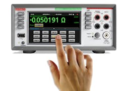
1. DMM6500 DC current measurements: 10pA sensitivity and 0.02% best 1-year accuracy. AC current measurements: 100pA sensitivity and 0.1% best 1-year accuracy.
One of the significant features of the DMM6500 is its low current sensitivity. It can resolve 10pA. For IoT and energy-harvesting products and for engineers that are trying to meet standby power requirements for power supplies, the very low current sensitivity and the accuracy can help the designer meet the new standards and help the test engineers verify the standby efficiency performance of their product. Among the measurement capabilities of the DMM6500 are:
- DCV and ACV: 100 nV –1,000 V (750 VAC) with 0.0025% 1-year DCV best accuracy
- Resistance: 1 µΩ – 100 MΩ
- DC Current: 10 pA – 10 A
- AC Current: 100 pA – 10 A
- Temperature: –200⁰C – 1820⁰C
- Capacitance: 0.1 pF – 100 µF
- Digitize Voltage:10 µV–1,000 V, up to 1Msample/s, 16 bits
- Digitize Current:10 nA–10 A, up to 1Msample/s, 16 bits
- Maximum measurement reading rate (integrating A/D): 20,600 readings/s
- Interfaces: LANLXI, USB-TMC standard, GPIB, RS-232, or TSP-Link optional
- Multichannel measurement capacity: 10 channels, two card options
- 5-in. touchscreen display
- Pinch and zoom simplicity
- Swipe screens and minimized menu depth for fast analysis
- Handy cursors for easy characterization of measurements with statistical data
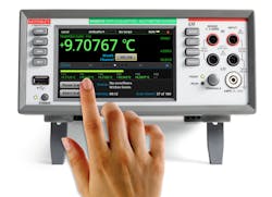
2. DAQ6510 Data Acquisition and Logging Multimeter System
In addition to the DMM6500 there is the DAQ6510 Data Acquisition & Logging Multimeter System (Fig. 2):
- DCV and ACV: 100 nV –1,000 V (750 VAC) with 0.0025% 1-year DCV best accuracy
- Resistance: 1 µΩ-100 MΩ
- DC Current: 10pA – 3A, AC Current: 100pA – 3A
- Temperature: –200⁰C – 1,820⁰C
- Capacitance: 0.1 pF – 100 µF
- Digitize Voltage: 10 µV – 1,000 V, up to 1Msample/s, 16-bits
- Digitize Current: 10 nA – 3A, up to 1Msample/s, 16-bits
- Maximum Switching Rate; 800 channels/s with solid state switch module
- Interfaces: LANLXI, USB-TMC standard, GPIB, RS-232, or TSP-Link optional
- Multichannel measurement capacity: 80 channels, 12 switch module options
Operation
- Simplifies setup, execution, and analysis of multichannel-measurement systems
- Quickly assess test status with at-a-glance monitoring during test execution
- Built-in plotting functions to display up to 20 different plots from 20 channels in one graph
- Easily drill down using pinch and zoom controls
- Conduct deeper analysis using cursors and statistical functions
- Can hold two plug-in switch cards for a maximum capacity of 80 two-pole channel connections
- Ability to select from 12 plug-in switch cards to perform a variety of tests

About the Author

Sam Davis
Sam Davis was the editor-in-chief of Power Electronics Technology magazine and website that is now part of Electronic Design. He has 18 years experience in electronic engineering design and management, six years in public relations and 25 years as a trade press editor. He holds a BSEE from Case-Western Reserve University, and did graduate work at the same school and UCLA. Sam was the editor for PCIM, the predecessor to Power Electronics Technology, from 1984 to 2004. His engineering experience includes circuit and system design for Litton Systems, Bunker-Ramo, Rocketdyne, and Clevite Corporation.. Design tasks included analog circuits, display systems, power supplies, underwater ordnance systems, and test systems. He also served as a program manager for a Litton Systems Navy program.
Sam is the author of Computer Data Displays, a book published by Prentice-Hall in the U.S. and Japan in 1969. He is also a recipient of the Jesse Neal Award for trade press editorial excellence, and has one patent for naval ship construction that simplifies electronic system integration.
You can also check out his Power Electronics blog.
Comment About the Article
To join the conversation, and become an exclusive member of Electronic Design, create an account today!

Leaders relevant to this article: