Analyzing Full-Wave Rectifiers With Capacitor Filters
Full-wave rectifiers with capacitor filters are, without question, the workhorse — and the unsung hero — of the modern electronic world and for the gadgets we have come to enjoy. That being said, it is surprising — and sadly so — that a symbolic solution set describing steady-state circuit performance has been absent.
In 1943, Schade gave a graphical solution.[1] In 1972, Millman outlined a few steps, stating that “no analytic expression can be given for….; it must be found graphically”.[2] In 1982, Williams presented a more analytical, albeit incomplete, attempt.[3] In 1991, Kassakian gave, in Example 3.1, a description for a half-wave rectifier[4] and two years later, Tarter showed several mathematical steps.[5] In 2004, Shepherd offer yet another result, although it was questionable.[6] There have been numerous other trials too long to list, but none have come close to providing a satisfactory result.
In this article, we will present a symbolic closed-form solution in its entirety, possibly for the first time. These developments have been made possible with the recognition of several crucial facts that had been sorely missed by all previous efforts.
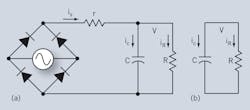
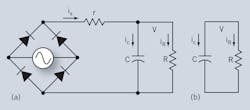
First of all, the source function driving the loaded filter was mistaken as A|sinωt| when diodes were conducting. The correct function shall be A|sin(ωt+θ)| since, at the time the diode commences conduction (time-zero), the driving source voltage is non-zero. Next, it is understood that, under steady-state operation, the circuit alternates periodically between two structures: Fig. 1a, which corresponds to the diode in conduction, and Fig. 1b, with the diode cutting out.
Fig. 1. Under steady-state operation, the rectifier alternates periodically between two structures (a) During conduction time, 0 < t < ton. At the start of diode conduction, the capacitor voltage begins with a finite voltage, designated as V0a (b) During non-conduction time, ton < t < T/2, the diodes cease conduction and the capacitor voltage begins with V0b.
Furthermore — and this is what previous efforts failed to discern — when Fig. 1a commences, the capacitor voltage begins with a finite voltage, designated as V0a in the following analysis. This finite voltage evolves into V0b when the diodes cease conduction, and the structure in Fig. 1b takes over. The key is that V0b must also cycle back to V0a when the diodes kick in again, and then the cycle repeats.
With the property of voltages wrapped around, i.e. continuity of states, in mind and referring to both Figs. 1a and 1b, the output node produces two Kirchhoff Current Law equations:
Here, t1 represents the instant diode conduction begins, and time-zero for analysis. Taking the Laplace transform of both equations produces:
The inverse Laplace transform yields the outputs corresponding to two time segments, 0 < t < ton and ton < t < T/2:
Here, both V0a and V0b, cyclic starting states, are embedded and yet unknown. As stated previously, V0a and V0b are linked by the following constraints; continuity of states:
Given two constraints in two unknowns, both unknowns can be solved with t1 and ton as parameters:
Besides the condition of continuity of states, two critical boundary conditions are also identified:
Eq. 9 and Eq. 11 allow:
Regrouping and collecting the appropriate terms yields:
Taking the ratio V0b/V0a also gives:
Eventually, both Eq. 13 and Eq. 14 can be consolidated, yielding an equation with a single unknown, ton:
This equation can be solved numerically for ton. Then, diode conduction time reductions follow, t1, using either Eq. 13 or Eq. 14, involving tan(ωt1). However, given modern mathematical software tools, e.g. MathCAD (MathSoft, Inc.), it is preferred to use V0a (t1, ton) and V0b (t1, ton) boundary Eq. 11 and solve both t1 and ton simultaneously. The following is an example.
EXAMPLE
Given a single-phase, 60-Hz, 120-V source-feeding 200-µF filter and a 57-⦠load with an assumed source series resistance of 0.5 â¦, the boundary Eq. 11 yields a conduction time reduction of t1 = 1.743 ms and a conduction duration of ton = 3.131 ms. Both boundary voltages, Eq. 9 and Eq. 10, are also obtained: V0a = 103.637 V, while V0b = 163.719 V. The rectified source, the output voltage in Eq. 5 and Eq. 6, and the rectified source current in steady state, are given in the plot in Fig. 2.
Fig. 2. In the steady state are the output voltage (red), rectified source (blue), and rectified source current (pink).
In the course of the above derivation, the capacitor's ESR was ignored. Once it is included, both the mathematical form and the formulation of boundary conditions grow more complicated. It is also to be noted that, so far, only the first-order circuit, the capacitor filter, is involved. In the real world, inductance, however small, is omnipresent. With the inclusion of inductance, e.g. along the input source line, the circuit becomes one of a second order with two first-order differential equations.
Other complications arise, e.g. three-phase sources and phase-controlled SCR, that can make analytical procedures extremely tedious. However, the concept of continuity of states and the need to identify the boundary conditions still correctly apply. Refer to Wu for further discussions.[7]
Given the waveforms in symbolic closed-form, additional analysis of harmonic contents, for example, can be easily performed. For a half-wave rectifier, readers are cautioned to apply the second boundary appropriately: V0b(T) = V0a.
By applying the concept of continuity of states and by identifying the critical boundary conditions, symbolic solutions in closed-form can be obtained for single-phase/full-wave and single-phase/half-wave rectifiers with capacitive filters.
REFERENCES
-
O.H. Schade; “Analysis of Rectifier Operation” Proceeding of IRE, Vol. 31, No. 7, July 1943
-
Jacob Millman, “Integrated Electronics-analog and digital circuits and systems” p.111, 1972, McGraw Hill
-
Keith L. Williams, “Mathematical Theory of Rectifier Circuits with Capacitor-Input Filters” Power Conversion International, p.42, Oct. 1982
-
John G. Kassakian, “Principles of Power Electronics”, p.38, 1991, Addison-Wesley
-
Ralph E. Tarter, “Solid-state Power Conversion Handbook”, p.229, 1993.
-
William Shepherd, “Power Converter Circuits”, p.20, 2004, Marcel Dekker
-
Keng C. Wu, “Power Rectifiers, Inverters, and Converters - accelerated steady-state approaches with closed-form solutions” ISBN 978-1-4357-2023-7, Oct. 2008, lulu.com.


