Is there a wireless power transfer standard?
Wireless power transfer is based on the Wireless Power Consortium’s WPC 1.1 Standard (July 2012) that facilitates cross compatibility of compliant transmitters and receivers. The Standard defines the physical parameters and the communication protocol used in wireless power transfer.
The Wireless Power Consortium’s global standard for compatible wireless charging is called Qi (pronounced “chee”), The Qi standard guarantees that any device carrying the Qi logo will work with any charging surface that carries the Qi logo, regardless of manufacturer or brand. Qi allows design freedom, product differentiation, and guaranteed wireless charging interoperability.
How does wireless power technology work?
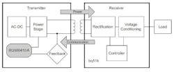
Wireless Power Transfer relies on magnetic induction between planar receiver and transmitter coils. Positioning the receiver coil over the transmitter coil causes magnetic coupling when the transmitter coil is driven. Flux couples into the secondary coil, which induces a voltage and current flows. The secondary voltage is rectified and transferred to the load, wirelessly. Wireless power transfer is usually controlled by two ICs: one transmits and another receives the transferred power, as shown in Fig 1.
How do the receiver and transmitter ICs provide the wireless transfer?
The power transfer receiver IC provides efficient AC/DC power conversion as required to comply with WPC 1.1 communication protocol. Control algorithms provide an effective and safe Li-Ion and Li-Pol battery charger– eliminating the need for a separate battery charger circuit.
By utilizing near-field inductive power transfer, a secondary coil embedded in the portable device can pick up the power transmitted by the primary coil. The AC signal from the secondary coil is then rectified and conditioned to apply power directly to the battery. Global feedback is established from the secondary to the primary in order to stabilize the power transfer process. This feedback utilizes the WPC 1.1 power communication protocol.
What determines the power transfer?
Power transfer depends on coil coupling, which depends on the distance between coils, alignment, coil dimensions, coil materials, number of turns, magnetic shielding, impedance matching, frequency and duty cycle. Receiver and transmitter coils must be aligned for best coupling and efficient power transfer. The closer the space between the two coils, the better the coupling. However, to account for housing and interface surfaces the practical distance is set to be less than 5 mm, as defined within the WPC Standard. Shielding is added as a backing to both the transmitter and receiver coils to direct the magnetic field to the coupled zone. Magnetic fields outside the coupled zone do not transfer power. Thus, shielding also serves to contain the wireless fields and avoid coupling to other adjacent system components.
Does the WPC 1.1 Standard set the operating environment for power transfer?
You can control power transfer by varying any one of the coil coupling parameters. However, for WPC compatibility, the transmitter-side coils and capacitance are specified and the resonant frequency point is fixed. Power transfer is regulated by changing the frequency along the resonance curve from 112 kHz to 205 kHz, (that is the higher the frequency is, the lower the power). Duty cycle remains constant at 50% throughout the power band and is reduced only once 205 kHz is reached.
What coil configurations are available?
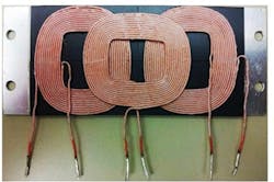
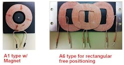
Fig. 2 shows the A6 three-coil configuration with a 70 x 20 mm charge surface area as well as the A1 single-coil with 18 mm x 18 mm charge space. The 70 mm by 20 mm A6 charge area is 400-percent larger than 18-mm by 18-mm area used by an A1 coil.
An A6 coil arrangement can achieve greater than 70-percent efficiency. The WPC Standard establishes coil and matching capacitor specification for the A6 transmitter. Although the transmitter is intended to drive an A6 three-coil array, it can also be used to drive a single A1 coil. For single coil operation the two outer coils and associated electronics are simply omitted.
The performance of an A6 transmitter can vary based on the design of the A6 coil set. For best performance with small receiver coils under heavy loading, it is best to design the coil set so that it is on the low end of the specified tolerance.
Does the WPC Standard set the coil characteristics?
The WPC standard describes the dimensions, materials of the coils and information regarding the tuning of the coils to resonance. The value of the inductor and resonant capacitor are critical for proper operation and system efficiency.
Why is capacitor selection important?
Capacitor selection is critical to proper system operation. The resonant tank requires a total capacitance value of 68 nF +5.6 nF center coil, which is the WPC system compatibility requirement. Capacitors chosen must be rated for at least 100 V and must be of a high quality C0G dielectric (sometimes also called NP0). They typically have a 5% tolerance, which is adequate. The designer can combine capacitors to achieve the desired capacitance value. Various combinations can work depending on availability.
Can you monitor power transfer efficiency?
Both Parasitic Metal Detection (PMOD) and Foreign Object Detection (FOD) can continuously monitor the efficiency of the established power transfer. This protects against power lost due to metal objects in the wireless power transfer path. Combining input power, known losses, and the value of power reported by the RX device being charged, the transmitter can estimate how much power is unaccounted for and presumed lost due to misplaced metal objects. Exceeding this unexpected loss indicates a fault and halts power transfer.
PMOD has certain inherent weaknesses as rectified power is not ensured to be accurate per the original WPC1.0 Specification. However, the FOD algorithm uses information from an in-system characterized and WPC1.1 certified receiver and it is therefore more accurate. Where the WPC1.0 specification requires merely the rectified power packet, the WPC1.1 specification additionally uses the received power packet that more accurately tracks power used by the receiver. As default, PMOD and FOD share the same threshold-setting resistor for which the recommended starting point is 400 mW.
How do the receiver and transmitter ICs communicate?
Communication within the WPC standard is from the receiver to the transmitter, where the receiver tells the transmitter to send power and how much. To provide regulation, the receiver must communicate with the transmitter whether to increase or decrease frequency. The receiver monitors the rectifier output and using Amplitude Modulation (AM), sends packets of information to the transmitter. A packet is comprised of a preamble, header, actual message and a checksum, as defined in the WPC standard.
The receiver sends a packet by modulating an impedance network. This AM signal reflects back as a change in the voltage amplitude on the transmitter coil. The signal is demodulated and decoded by the transmitter-side electronics and the frequency of its coil-drive output is adjusted to close the regulation loop.
About the Author

Sam Davis
Sam Davis was the editor-in-chief of Power Electronics Technology magazine and website that is now part of Electronic Design. He has 18 years experience in electronic engineering design and management, six years in public relations and 25 years as a trade press editor. He holds a BSEE from Case-Western Reserve University, and did graduate work at the same school and UCLA. Sam was the editor for PCIM, the predecessor to Power Electronics Technology, from 1984 to 2004. His engineering experience includes circuit and system design for Litton Systems, Bunker-Ramo, Rocketdyne, and Clevite Corporation.. Design tasks included analog circuits, display systems, power supplies, underwater ordnance systems, and test systems. He also served as a program manager for a Litton Systems Navy program.
Sam is the author of Computer Data Displays, a book published by Prentice-Hall in the U.S. and Japan in 1969. He is also a recipient of the Jesse Neal Award for trade press editorial excellence, and has one patent for naval ship construction that simplifies electronic system integration.
You can also check out his Power Electronics blog.
Comment About the Article
To join the conversation, and become an exclusive member of Electronic Design, create an account today!

Leaders relevant to this article: