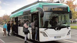
Battery-Powered Bus Employs Fast Charging for Regular Operation
Electric vehicles are supposed to make urban transport more environmentally friendly. Using buses for short-range public transportation is a good way of helping to implement this vision: fixed routes and stops make it easier to plan and provide the requisite infrastructure. In addition, public transport sets an example to the wider public. However, electric buses will only gain acceptance if they adapt to established operational practices and do not create a need for additional vehicles or personnel. This poses some challenges: Regular urban public transport buses travel up to 400 kilometers a day without returning to the depot. To supply the electric energy this requires, huge batteries would be needed, for which there is not enough space available in a bus. The alternative is to quickly recharge the vehicle’s battery while it is serving its route—for example, while the bus is waiting at the terminus. This requires high charging capacity.
To answer these restraints, scientists at the Fraunhofer Institute for Transportation and Infrastructure Systems IVI in Dresden, Germany, working with several partners in an EDDA Bus project, developed a solution that permits fast, uncomplicated recharging. EDDA Bus is part of the Fast Charging Systems for Electric Buses in Public Transport joint research project funded by the German Federal Ministry of Education and Research (BMBF). The solution is based on four core technologies: the Dresden-based company M&P GmbH designed a charging station with very high charging capacities; HOPPECKE Advanced Battery Technology GmbH supplied special batteries designed for such high power capacities; Vossloh Kiepe GmbH was responsible for adapting the power electronics; and finally, the heart of the development work is the contact system located on the roof of the bus, which was configured by Fraunhofer IVI together with Schunk Bahn- und Industrietechnik GmbH.
Charging Station
There are two different approaches to outside the bus depot. The advantage of recharging the energy storage inside of the bus depot, at terminal stations, and at stations where the bus usually stops for a longer period of time is that the range can be extended considerably without any impediments to the operating procedure, provided the battery has been designed appropriately. In many cases, it will even be possible to fully emulate the operating procedure of conventional diesel buses. For this kind of recharging routine, comparatively small batteries can be used, which are quite easily integrated into the vehicles.
If energy is supplied to the vehicle at underway bus stops along with recharging in the depot and at terminal stations, you can use batteries with even smaller energy content. Thus, the time needed for recharging at the terminal stations will be shorter, reducing the overall risk of accumulated delays.
To recharge enough energy in the respective available amount of time requires charging stations with different charging capacities. Recharging during the passenger exchange at underway bus stops, for example, is only practical with a charging capacity of 400 – 500 kW.
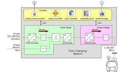
Two charging stations concepts were developed by M&P motion control & power electronics GmbH from Dresden. One approach was the fast charging station and the other was for a pulse charging station. Figure 1 is a diagram of the fast charging station. Its characteristics include:
- Input AC grid: 10/20 KV, 400 VAC
- Alternative input DC grid: 675 – 1000 VDC
- Connecting power: 270 kVA
- Output voltage: 0 – 750 VDC
- Charging capacity: max. 250 kW
- Efficiency: >95 %
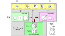
The pulse charging station has the configuration shown in Fig. 2. Its characteristics include:
- Grid input: 400 VAC, 63 A
- Connecting power: 44 kVA
- Internal storage: 2.6 kWh (4.0 kWh optional)
- Internal storage type: Supercapacitors
- Output voltage: 0 – 750 VDC
- Charging capacity: max. 600 kW (optional max. 700 kW)
- Efficiency: >92 %
Electrical Contact System
In collaboration with Fraunhofer IVI, Schunk Bahn- und Industrietechnik GmbH developed the electrical contact system, consisting of a pantograph, a contact head and a roadside contact hood (Fig. 3).
This development’s aim was to safely transmit high electric capacities, and the currents associated with them, to a stationary vehicle via a compact and robust system. To enable the automation of the process, this system was developed as an alternative to plugin systems, which need to be connected manually.
With this construction, a fast contact closure is possible using only one actuator for positioning the contact head inside the roadside contact hood. It doesn’t require additional actuators (e.g., servo motors).
For the contact head, six powerful contacts were housed in a small installation space. There are two contact poles—one positive, one negative—on each side. Fitted to the top, there is a ground contact and a control pilot, which monitors the grounding. This means our system meets the most stringent safety requirements. Schunk Bahn- und Industrietechnik GmbH developed heat-stable components for the contact system. This was necessary because, in contrast to streetcars, for instance, where energy is transferred while the vehicle is moving, transferring power to a stationary vehicle generates high local temperatures that might damage conventional components.
The charging process is very straightforward. We don’t want to burden drivers with extra tasks. All drivers have to do is position the bus beneath the contact hood at the charging station. While doing so, they can use a marker at the edge of the curbstone for orientation. An acoustic signal assists drivers when positioning the bus at the stop. To ensure some leeway, the contact head adjusts itself on a slide rail and then docks with the contact hood. The charging process begins automatically. During charging, drivers can follow the battery’s charge status on a display. If required, the charging process can also be interrupted.
The developed contact system grants the bus a generous positioning tolerance regarding the roadside contact hood, which will pose no problem for the driving staff. In addition, the contact system balances out sideway movements of the vehicle during the so-called kneeling.
Communication Between Charging Station and vehicle
With the help of radio-based wireless communication between vehicle and charging station and a sufficiently precise detection of the vehicle position at the bus stop, a safe contacting process is initialized by corresponding algorithms. This procedure fulfils the following system requirements:
- Release of the voltage at the charging station output point and at the vehicle-bound part of the contact system only after successful establishment of contact with authorized vehicles
- Demand-based connection of the charging station ensures high system efficiency
- Extension of the contact system’s moveable parts into the clearance gauge only when clearance gauge is blocked by the vehicle in the appropriate area of the bus stop
- Detection of the vehicle’s direction of travel and position within the bus stop enables the serving of different charging locations by one charging station
Implementing the technology in regular operation creates specific additional requirements for the system. The development aims in this case were to avoid making additional demands of the driver and to not cause any restrictions for the passengers.
Accordingly, the automated charging process must be able to identify all relevant system states and react to them appropriately in case of any discrepancies. An additional challenge was the distribution of the necessary interaction among several subsystems, which are generally provided by different collaborative partners. For this purpose, the respective automation tasks and interfaces had to be clearly identified. By doing so, the different subsystems can now be further developed, extended and recombined within other applications.
Under the monitoring of TÜV Rheinland, a safety and operating concept was compiled based on the technical standard DIN EN 618511. As a first step towards the overall concept, a risk analysis was conducted in compliance with the standard IEC 615082. Implementation of the derived tasks and requirements was monitored and approved by TÜV Rheinland.
The following framework conditions for the design of the automated charging process were derived from the knowledge gathered at Fraunhofer IVI regarding the requirements for its use in regular bus operation. Subsequently, they were implemented by the automation solution.
- Each driver must be able to position a bus at the curb with an accuracy of 40 cm in the direction of travel and 30 cm laterally. The approach of the charging station is facilitated by “Kombibord” curbstones.
- The automated process must be easily integrated into the drivers’ regular work routine. The only information that the drivers will be provided with is status information about the charging process, but they will retain the option of canceling or terminating the charging process.
- The roadside contact hood has to be installed so that its lower edge remains at a height of at least 4.50 m above the road at all times.
- Energy transmission is to start within 0.5 sec of the contact closure.
- Energy transmission is to be initiated only if electric safety can be ensured.
- If a discrepancy or deviation is detected by one of the subsystems, the charging process is to be terminated automatically.
As demanded by the DIN EN 61851, the charging system is constructed as an electrically insulated system with a galvanic isolation from the grid input. This is realized by the installation of an insulating transformer within the charging station. During the recharging process, the electric safety for persons and facilities is ensured by connecting the electric grounding in the bus stop area with the vehicle’s chassis and additionally by monitoring the connection during the time of the energy transmission. Furthermore, an insulation monitor continuously checks the insulation resistance of the closed system circuit consisting of all components involved in the charging process. DC contactors inside the charging station and inside the vehicles serve to ensure the fast and secure electrical separation in case of a fault. These electrical switches are also used to realize the permanent separation of the contact system’s electrically active components, which can be touched by the maintenance staff while no charging process is going on.
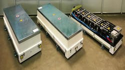
The batteries installed in the EDDA-Bus, which were developed by HOPPECKE Advanced Battery Technology GmbH (Zwickau), are characterized by their high charging capacity. They have a modular design and can be combined to different-size packs for installation in buses (Fig. 4). Its characteristics are:
- Cell technology: Lithium Ion pouch design NMC
- Number of modules: 3
- Total energy content: 86kWh
- Charging capacity: 450kW
- Cooling system: liquid
The modular concept developed by Vossloh Kiepe GmbH combines the tried-and-tested traction equipment of serial hybrid buses with fast chargeable batteries and their corresponding charging technologies:
- Integration of the recharging functionalities
- Balancing of the battery modules while driving
- Electrification of the auxiliaries (air compressor, power steering pump)
- Enhancement of vehicle network services
- Safety and energy management
During both the fast charging process and the recuperation of braking energy, the individual battery modules can over time develop differing states of charge, e. g. due to temperature variations or varying module-internal resistances.
Experience gained in other projects shows that the complete battery displays a better performance when its individual modules are balanced. Because of this, Vossloh Kiepe developed an energy management system that evens out the battery modules’ state of charge while on the road. The balancing results in a more uniform load distribution over the modules, thus maximizing their life cycle.
The overall system, consisting of the battery bus and the charging station, was approved by the TÜV Rheinland.
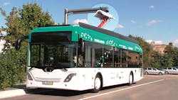
From Nov. 3, 2014, until Jan. 30, 2015, the Dresdner Verkehrsbetriebe AG tested all developed components in regular operation on a 14.4 km-long segment of a bus line. Subsequently, the data from over 9,500 kilometers travelled during the field test was analyzed and interpreted. Figure 5 shows the bus in operation.
Both the fast charging station (250 kW) and the pulse charging station (450 kW during the field test) were erected across from the Dresden-Gruna bus depot and tested as well. Due to the energy-efficient design of the bus, it was possible to recharge the energy consumed during one route cycle within 4.5 minutes of fast charging, so that no interferences with the regular schedule were caused by the recharging process.
The key technologies developed within project EDDA-Bus proved themselves extremely reliable in the field test. Vehicle failures were almost exclusively brought about by the “teething troubles” of components that are not immediately connected to the electric propulsion (door control, heating, air compressor, etc.)
|
*IVI is an abbreviation of the institute's German name: Institut für Verkehrs- und Infrastruktursysteme. The letters do not correspond to the English translation, but since it is the common term used to refer to this group, it was kept like that in English. |
|
