Download this article in PDF format.
“Analog design is now a combination of transistors and ICs that provide high functionality in analog signal processing,” says Bob Dobkin, VP of Engineering and Chief Technical Officer of Linear Technology Corp. “And, analog design is in greater demand now than ever before.”
A key analog IC is the operational amplifier, commonly called an op amp. One of the newest op amps is Linear Technology’s LTC2063, a single low-power, zero-drift, 20-kHz IC. The LTC2063’s high-precision input characteristics allow use of large-value feedback network resistors, keeping power consumption low without compromising accuracy, even at elevated temperatures. Its operational features include:
- Supply voltage: 1.7 V to 5.25 V
- Supply current: 1.3 μA (typ), 2 μA (max) on a 1.8-V supply
- Maximum input offset voltage: 5 μA at 25°C
- Maximum drift: 0.06 μV/°C from –40°C to 125°C
- Maximum input bias current: 15 pA at 25°C, 100pA from –40°C to 125°C
- Open loop gain (AVOL): 140 dB (typ)
- Low charge power-up for duty-cycled applications
Rail-to-rail inputs and outputs simplify single supply use and enhance dynamic range. An integrated electromagnetic-interference (EMI) filter provides 114-dB EMI rejection at 1.8 GHz. With low 1/f noise inherent to its zero-drift architecture, the LTC2063 is well-suited for amplifying and conditioning low-frequency sensor signals in high-temperature industrial and automotive systems as well as portable and wireless-sensor-network applications.
Zero-drift amplifiers like the LTC2063 achieve low input offset voltage and 1/f noise by heterodyning dc and flicker noise to higher frequencies. In early zero-drift amplifiers, this process resulted in idle tones at the self-calibration frequency, often referred to as the chopping frequency. These artifacts made early zero-drift amplifiers difficult to use. The advanced circuit techniques used by the LTC2063 suppress these spurious artifacts, allowing for trouble-free usage.
For applications with high source and feedback impedances, input current noise can be a significant contributor to total output noise. For this reason, it is important to consider noise current interaction with circuit elements placed at the amplifier’s inputs.
Low input current noise is achieved by utilizing MOSFET input devices and self-calibration techniques to eliminate 1/f current noise. As with all zero-drift amplifiers, current noise increases at the offset-nulling frequency.
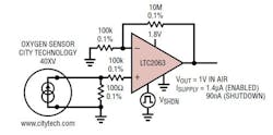
1. This micropower oxygen sensor application leverages the LTC2063 zero-drift op amp.
The input bias current of zero-drift amplifiers has different characteristics than that of a traditional op amp. The specified input bias current is the dc average of transient currents that conduct due to the input stage’s switching circuitry. In addition, junction leakages can contribute additional input bias current at elevated temperatures. With careful design and use of an innovative boot-strap circuit, the input bias current of the LTC2063 does not exceed 20 pA at room temp and 100 pA over the full temperature range. This minimizes bias-current-induced errors even in high impedance circuits.
Thermocouple Effects
To achieve accuracy at the microvolt level, you must consider thermocouple effects. Any connection of dissimilar metals forms a thermoelectric junction and can generate a small temperature-dependent voltage. These thermal EMFs can be annoying error sources in low-drift circuits. Connectors, switches, relay contacts, sockets, resistors, and solder are all candidates for significant thermal EMF generation. Even junctions of copper wire from different manufacturers can generate thermal EMFs of 200 nV/°C, which significantly exceeds the maximum drift specification of the LTC2063.
The LTC2063 is available in SOT-23 and SC70 packages. The SC70 version includes a shutdown mode that reduces current consumption to just 90 nA when the amplifier is not in use. You can shut down the LTC2063 by tying below V_. If you do not need the shutdown feature, tie the pin to V+. A 50-nA current source pulls the pin high to automatically keep the amplifier in the ON state when the pin is floated, although this may not be reliable at elevated temperatures due to board leakage.
In noisy environments, connect a capacitor between and V+ to prevent noise from changing the shutdown state. If is in danger of being pulled beyond the supply rails, place a resistance in series with the pin to limit the resulting current.
Gas Sensor
Figure 1 shows a low-power precision gas sensor circuit operating in an oxygen-level range of 0% to 30%, with a nominal output of 1 V in normal atmospheric oxygen concentrations (20.9%) when the gas sensor is fully initialized. Total active power consumption is less than 2.1 μA on a single rail supply.
Because this gas sensor produces 100 μA in a normal oxygen environment, it requires a 100-Ω load resistor, with the resulting input signal typically around 10 mV. The LTC2063’s rail-to-rail input means no additional dc level shifting is necessary, all the way down to very low oxygen concentrations.
Due to the extremely low input offset voltage of the LTC2063, which is 1 μV typically and 5 μV maximum, it is possible to gain up the mV-scale input signal substantially without introducing significant error. In the configuration, with a non-inverting gain of 101 V/V, the worst-case input offset results in a maximum of 0.5 mV offset on the 1-V output, or 0.05% error.
Although the 100-kΩ resistor in series with the gas sensor does not strictly have the same precision requirement as the 10-MΩ and 100-kΩ resistors that set the gain, it is important to use a similar resistor at both input terminals. This helps to minimize additional offset voltage at the inputs due to thermocouple effects; hence, the similar 0.1% precision requirement.
RTD Sensor
Another application (Fig. 2) involves a low-power platinum resistance temperature detector (RTD) sensor circuit that draws only 35-μA total supply current on a minimum 2.6-V rail. It is accurate to within ±1°C at room temperature, including all error intrinsic to the Vishay PTS Class F0.3 Variant RTD. It covers the –40°C to 85°C temperature range in 10-mV/°C increments and produces an output of 1 V at nominal room temperature of 25°C.
2. The LTC203 is a key component in this micropower resistance-temperature-detector application.
The LTC2063’s extremely low typical offset of 1 μV and typical input bias current of 3 pA allows for the use of a very low excitation current in the RTD. Thus, self-heating is negligible, improving accuracy.
An LT5400-3, B-grade, is used to provide a ±0.025% matched resistor network that is effectively a precision 131:1 voltage divider. This precision divider forms one half of a bridge circuit, with the 0.1% 110-kΩ and RTD in the other branch. The 110-kΩ resistor’s precision requirement is to ensure matching with the RTD. The 11-kΩ R2 serves to deliver a dc offset for the entire bridge so that the output is 1V at room temperature. Bridge imbalances can lead to error—to reduce additional lead resistance, you should minimize the length of the leads that connect to the RTD.
The LT6656-2.048 reference IC provides a known excitation current in the RTD at each temperature of operation, and acts as a supply for the LTC2063, while using less than 1 μA itself. The LT6656 can accept input voltages between 2.6 V and 18 V, allowing for flexibility in selection of supply voltage while maintaining a fixed output range. The LT6656 reference can easily source the 35 μA required to run the entire circuit thanks to the LTC2063’s 2-μA maximum supply current and its ability to handle microvolt signals produced by the RTD operating with low excitation current.
Take care to minimize thermocouple effects by preventing significant thermal gradients between the two op-amp inputs. To minimize error due to drift over the entire temperature range, choose low-temperature coefficient feedback and series resistors.
High-Side Current Sense
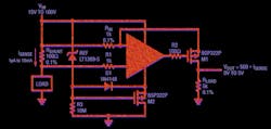
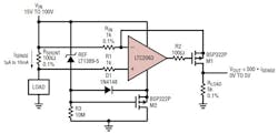
Figure 3 shows a high-side current sense circuit that draws 2.5 μA to 12.5 μA of supply current, depending on VIN, while measuring currents from 1 μA to 10 mA over a 15-V to 100-V input voltage range.
3. In this case, a high-side current-sense circuit takes advantage of the LTC2063’s low typical input offset voltage and low input bias current.
The LTC2063’s low typical input offset voltage of 1 μV and low input bias current of 3 pA contribute output errors that are much smaller than the error due to precision limitations of the resistors. Thus, output accuracy is mainly set by the accuracy of the resistors RSHUNT, RIN, and RLOAD.
The LT1389-5 5-V reference, along with the bootstrap circuit composed of M2, R3, and D1, establishes a very-low-power, isolated 5-V rail that protects the LTC2063 from reaching its absolute maximum voltage of 5.5 V while allowing for much higher input voltages. The LTC2063’s gain-bandwidth product is 20 kHz, so use this circuit to measure currents that do not change faster than a 2-kHz rate.
About the Author

Sam Davis
Sam Davis was the editor-in-chief of Power Electronics Technology magazine and website that is now part of Electronic Design. He has 18 years experience in electronic engineering design and management, six years in public relations and 25 years as a trade press editor. He holds a BSEE from Case-Western Reserve University, and did graduate work at the same school and UCLA. Sam was the editor for PCIM, the predecessor to Power Electronics Technology, from 1984 to 2004. His engineering experience includes circuit and system design for Litton Systems, Bunker-Ramo, Rocketdyne, and Clevite Corporation.. Design tasks included analog circuits, display systems, power supplies, underwater ordnance systems, and test systems. He also served as a program manager for a Litton Systems Navy program.
Sam is the author of Computer Data Displays, a book published by Prentice-Hall in the U.S. and Japan in 1969. He is also a recipient of the Jesse Neal Award for trade press editorial excellence, and has one patent for naval ship construction that simplifies electronic system integration.
You can also check out his Power Electronics blog.


