Controller Design for DCM-Operated Boost Converter Using System Identification

Power electronics converters require negative feedback to provide a suitable output voltage or current for the load. Obtaining a stable output voltage or current in presence of disturbances like input voltage changes and /or output load’s changes seems impossible without some form of control. Although control engineering has considerable progress over recent decades, most applications use PID (Proportional Integral Derivative) controllers, because of their low price and simplicity. Generally speaking, using derivative term is not so common in power electronics converters control. Usually a P or PI controller is all that is required. Designing a classical P or PI controller for a power electronics converter is started by obtaining the model of converter. Modeling is the process of formulating a mathematical description of the system. Obtaining the mathematical model of system is the first step toward designing a controller in model base controller design techniques. Switching power converters are nonlinear variable structure systems. Various techniques can be found in literature to obtain a Linear continuous Time Invariant (LTI) model of a dc-dc converter. Among the most well-known methods are current injected approach, circuit averaging and state space averaging.
Table 1 compares CCM and DCM in dc-dc converters.
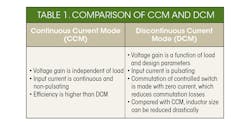
One important feature of a boost converter is the Non-Minimum Phase (NMP) characteristic, which is due to the Right Half Plane (RHP) zero in its control to output voltage transfer function. NMP effect deteriorates the control and stability behavior of the converter. DCM operation is an available alternative to CCM. In this case, the RHP zero places in high frequencies, usually higher than switching frequency and the boost converter mainly behaves like a converter with a single pole. Considering the disadvantage of DCM operation like high current ripple and low efficiency, in some special applications when control is important, power circuit designers intentionally design the controller to operate in DCM operation.
Related Works
The foundation for State Space Averaging (SSA) was laid down in Middlebrook RD et al. (1977). SSA is appropriate to describe converters that work in CCM while is less suitable for converters work in DCM. The first attempt to model Discontinuous Conduction Mode (DCM) is presented in. Cuk S et al. (1977). Accurate small signal models for DCM operation were developed by Sun J et al. (2001). The current injected method (Kislovski, et al (1991) and Mohan et al. (2003)) can do the job of modeling in either CCM or DCM. A unified SSA based method to develop both CCM and DCM was developed by Suntio T. (2006). Circuit averaging gained a lot of attention recently due to its generality (Hren A. et al.2005). A comprehensive survey of the modeling issues can be found in Maksimovic et al. (2001).
Application of different control methods to power electronics converters has been studied in many papers. For example, feedback linearization (Sanders GC, et al. (1986), sliding mode control (Sira-Ramirez H, et al. (1987)), PID control (Venkatanarayanan S, et al. (2014) and design (Rodriguez H, et al. (2005)) has been applied to Cuk converter, Linear Matrix Inequality (LMI) control has been applied to conventional boost by Kumar PR (2015). Discrete time controller has been designed for a boost converter in Alkrunz et al. (2016). A cascade state space controller is designed for buck mode of bidirectional dc-dc converter in Ocilka M, et al. (2010). PID control of SEPIC converter is studied in Veenalakshmi et al. (2014).
Converter Model
Assume a boost converter with the following parameter values:
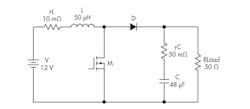
1. Boost converter used in simulations.
MOSFET M has on-resistance of 100mΩ and diode D has forward voltage drop of 0.8 V and forward resistance of 1mΩ. Switching frequency is 25KHz and duty ratio is 0.462. Figure 2 shows the steady state inductor current:
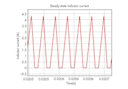
2. Steady-state inductor current.
As shown in Fig. 2, inductor current returns to zero during each switching period. In order to obtain the small signal model around the given operating point, a small change is applied to the duty ratio and the corresponding output voltage is recorded. Figures 3 and 4 show the change in duty ration and output voltage, respectively.
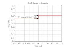
3. Change in duty ratio (from 0.462 to 0.472).
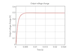
4. Change in output voltage.
System identification uses statistical methods to build mathematical models of dynamical systems from measured input-output data. In system identification, there are two approaches: Parametric and non-parametric identification. In the parametric identification problem, a mathematical structure is assumed to govern the system and the identification process is focused only on determination of unknown parameters for this structure that optimize the representation of the system. Nonetheless, in a non-parametric identification, the structure of these equations is also unknown. Nonparametric regression and spectral techniques correspond to this kind of techniques. Matlab has a powerful system identification toolbox. It has a user-friendly Graphical User Interface (GUI) that makes it easy to use. Using Matlab’s system identification toolbox, the following model is obtained for the input-output data shown in Figs. 3 and 4.

Control is done with a simple PI controller. Assume that phase margin of 80 deg. and bandwidth of 500 Rad/s is required. Using frequency domain design techniques (Ogata, 2003):

Simulation results:
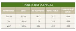
Performance of designed controllers are tested with the aid of following scenario: Load resistance goes from Rload= 50Ω to Rload= 25Ω at t= 50ms, input source voltage changes from Vs= 12V to Vs= 18V at t= 100ms and reference voltage has been changed from Vref= 30V to Vref= 40V at t= 150ms. This scenario is summarized in Table 2.
Simulation results are shown in Fig. 5.
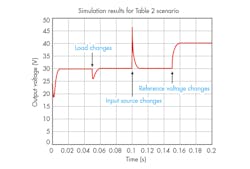
5. Simulation results.
As seen in Fig. 5, output has zero steady state error. Controller keeps output voltage constant despite of changes in load resistance and input voltage.
References:
- Alkrunz M, Yazıcı I(2016). Design of discrete time controller for the dc-dc boost converter. Sakarya University Journal, vol. 4, pp.75-82
- Basso, C. (2008). Switch-Mode Power Supplies, McGraw-Hill, New York
- Cuk, S. and Middlebrook, R.D. (1977). “A general unified approach in modeling switching DC-to-DC converters in discontinuous conduction mode,” in Proc. IEEE Power Electronics Special Conf. pp. 36–57
- Hren A., Slibar P. (2005), “Full order dynamic model of SEPIC converter,” Proceedings of the IEEE International Symposium on Industrial Electronics, Dubrovnik, Croatia, vol. 2, pp. 553-558
- Kislovski, A.S., Ridl, R. and Socal, N. (1991). Dynamic analysis of switching mode dc-dc converter, Van Nostrand Reinhold, New York.
- Kumar, P.R., Kumar, S.G., Sandeep, K. and Arun, N. (2015). “LMI control of conventional boost converter,” Indian Journal of Science and Technology, Vol. 8, pp. 50-52
- Maksimovic, D., Stankovic, A.M., Tottuvelil, V.J. and Verghese, G.C. (2001). “Modeling and simulation of power electronic converters,” Proc. IEEE, vol. 89, no. 6, pp. 898–912
- Middlebrook, R.D. and Cuk, S. (1977). A general unified approach to modeling switching-converter power stages. Int. J. Electron., vol. 42, no. 6, pp. 521–550
- Mohan, N., Undeland, T. and Robbins, W. (2003). Power electronics devices, converters appication and design, John Wiley and Sons, New York.
- Ocilka, M. and Beres, T. (2010). State space controller for bidirectional dc-dc converter buck mode. Scientific conf. of young researchers, Kosice, Slovakia.
- Ogata, K. (2003). Modern control engineering, Prentice Hall, New Jersey.
- Rodriguez, H., Ortega, R., Astolfi, A. (2005). Adaptive partial state feedback control of the DC-to-DC Cuk converter. Proceedings of the 2005 American Control Conference, Vol. 7, pp. 5121-5126.
About the Author
Farzin Asadi
Farzin Asadi is a professor in the mechatronics engineering department at Kocaeli University in Kocaeli, Turkey. He can be reached at [email protected].
Nurettin Abut
Nurettin Abut is a professor in the electrical engineering department of Kocaeli University in Kocaeli, Turkey. He can be reached at [email protected].
Comment About the Article
To join the conversation, and become an exclusive member of Electronic Design, create an account today!

Leaders relevant to this article: