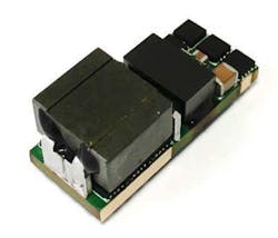
Power Stamps are 48-V direct dc-dc conversion-to-POL modules that can provide the higher power density required for future data centers. The new Power Stamp Alliance (PSA) specifies a standard Power Stamp footprint and functions that deliver multiple-sourced, standard modular board-mounted solutions for data centers (Fig. 1). The Founding Members of the Power Stamp Alliance are Artesyn Embedded Technologies, Bel Power Solutions, Flex, and STMicroelectronics.
1. Shown is a Power Stamp module solution.
These Power Stamps primarily target high-performance computers and servers being used in large data centers, many of which follow the principles of the Open Compute Project (OCP). OCP’s mission is to design and enable the delivery of the most efficient server, storage, and data-center hardware designs for scalable computing.
By creating and sharing a specification for a standard product footprint and functions, the Power Stamp Alliance has created a multi-vendor ecosystem to assure practical levels of alternate source capability to server and storage system manufacturers. At the same time, its encouraging a competitive supply chain through differentiation in topology, circuitry, and performance from multiple, independent manufacturers.
The first processor architectures addressed by the Power Stamp Alliance include the Intel VR13 Skylake CPUs, Intel VR13-HC Ice Lake CPUs, DDR4 memories, IBM POWER9 (P9) processors, and high-current ASIC and/or FPGA chipsets supporting the SVI or AVS protocols.
Serial VID Interface (SVI) is a two-wire (clock and data) bus that connects a single master (processor) to one or more slaves (voltage regulators). Adaptive voltage scaling (AVS) is a closed-loop, dynamic-power-minimization technique that reduces power based on the actual operating conditions of the chip; i.e., the power consumption is continuously adjusted during the run time of the chip.
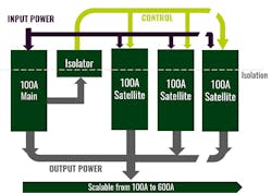
The electrical concept of power stamps uses the principle of a discrete controller or Main Stamp unit controlling up to five Satellite Stamp units that combine to provide more than 600-A total current capability. The size and powertrain footprint of the Main and Satellite power stamps are the same, simplifying the design process for OEMs. To handle increasing power demands of processor and memory devices, the PSA specification provides a scalable solution that can be used in tandem with existing power-conversion devices.
“The kind of plug-and-play solutions enabled by the Power Stamp Alliance should appeal not only to the hyperscale data-center builders, but also to high-performance computer makers and telecom equipment suppliers as the stamps themselves should be easy to integrate into their systems,” says Maggie Shillington, data centers, cloud and IT Infrastructure research analyst at IHS Markit. “Driving efficiency and power density down to the board level within an open framework follows the values of initiatives such as the Open Compute Project and Project Scorpio, and allows each vendor to focus on their own expertise and experience.”
This Alliance will mean there will be no single source for modules that combine DOSA (Distributed power Open Standards Alliance) and POLA (Point of Load Alliance) standards. The PSA is similar to both DOSA and POLA. DOSA products share common mechanical pinouts and footprints, and POLA products share common silicon.
The PSA complete specifications, drawings, and pin-out descriptions for Main and Satellite power stamps can be found at: http://www.powerstamp.org/specifications/.
Closer Look at Stamp System Components
2. Three main functions comprise the basic configuration of the PSA system.
As seen in Fig. 2, the PSA system includes three functions:
- Main Stamp unit
- Satellite Stamp unit
- Controller
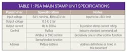
Table 1 lists the specifications for the Main Stamp unit. The PSA Satellite Stamp’s function is to extend the power and current rating of the standard PSA family of products, as listed in Table 2. The controller IC can be an external STPDDC60 or a PSA60 for integration into the Main Stamp unit. The STPDDC60 multiphase digital controller supports up to six interleaved converters to efficiently handle output power levels from 50 to over 250 W (2.5 V at 100 A) and is fully programmable through PMBus. The PSA60 is a digital multi-satellite controller optimized for PSA designs.
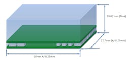
The PSA Main Stamp is a multi-satellite controller with complete control logic and protection, providing a high-performance high-efficiency, step-down dc-dc voltage regulator. It’s optimized for advanced microprocessor, memories, and ASIC power with direct conversion from a 48-V bus. Fig. 3 shows the specified Main Stamp package. There’s a maximum height spec; each supplier is permitted to have different heights using their individual designs as long as they don’t exceed the maximum height.
3. The Main Power Stamp package has a maximum height spec.
The control loop is based on the Digital STVCOT, a patented STMicroelectronics control method based on constant on-time controllers, rather than PWM fixed frequency. In a fixed-frequency controller, each phase duty cycle is determined by closing the total voltage loop and the current balancing loop that compares the phase current with the average phase current. In contrast, with STVCOT the switching period of each phase is determined by the total voltage loop, while the on time is chosen to equalize the phase currents and adjust the mean frequency to a desired switching rate under steady-state conditions.
The STVCOT control system uses the instantaneous switching frequency to determine the sudden increase of load so that it can trigger the turn-on of all phases. This helps minimize the latency of the energy-proportional design without excessive cost for the control-voltage-error ADC, digital design, and current-monitoring ADC.
The Main Stamp reads the current information delivered from Satellite Stamps. With this information, the Main Stamp adjusts the control signal sent to the Satellites in order to equalize the average current carried by each cell. All required parameters of both the control loop and power-management features are programmable through dedicated PMBus commands.
To guarantee the load is safe under all circumstances, there’s a complete set of protection functions: output voltage/current, input voltage/current, feedback disconnection, temperature, input/output powers, and catastrophic fails.
The Main Stamp supports the CPU-link bus-driven power state command, which improves the overall conversion efficiency by shedding satellites and entering the pulse-skip mode. You can enable these features regardless of the command issued through the CPU bus (either SVI or AVS), which makes it possible to optimize the conversion efficiency in every instant of the conversion.
Satellite Shedding allows the number of working cells to be adjusted according to the delivered current still maintaining the benefits of the multi-cell regulation. The end user can program switch-over threshold for every cell number transition, with hysteresis. Sleeping Satellites are reset in case of dynamic voltage transitions.
The Main Stamp is fully compliant with the Intel VR13 PWM rev 1.1, document # 544905 and the Intel SVI protocol Rev1.7, document # 456098. Different platforms may require different pull-up impedance on the CPUI-Link bus. Impedance matching and spacing must be followed.
PSA’s Main Stamp is also fully compliant with the PMBus specification part I and part II, revision 1.2, and with Part III, Revision 1.3. Main Stamps are fully compatible with the PMBus specification for read/write access in the byte, word, and block mode.
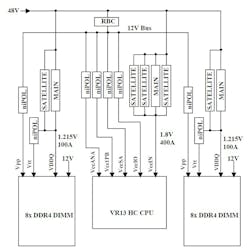
Figure 4 illustrates a typical Power Stamp system that includes Main and Satellite units as well as the non-isolated POLs. Also shown are the VR13 CPU and DIMM memories.
4. Typical PSA power distribution consists of a 100-A Main Stamp with multiple Satellites for a high-performance, high-efficiency, step-down dc-dc output voltage using non-isolated POL (niPOL) regulators.
The Main and Satellite Power Stamp are isolated dc-dc converters housed in an industry standard form factor defined by the Power Stamp Alliance. They convert a 48 V bus voltage into a low voltage suitable for typical server’s motherboard subsystems.
The Satellite Power Stamp is the basic building block for large dc-dc converter subsystems featuring scalable output power and efficiency. The Satellite is an isolated power train based on a proprietary phase-shifted full-bridge topology. It’s part of a family of industry-standard products defined by the Power Stamp Alliance.
Preliminary Data
Because PSA was formally introduced as recent as March 2018, associated product descriptions are still preliminary. One of these products is STMicroelectronics’ PSA60, an IC controller that can drive multi-phase arrays of up to six paralleled Satellites. PSA60 is a high-performance digital controller featuring the patented resonant/non-resonant STVCOT control loop that allows it to implement a high efficiency dc-dc converter in single-stage conversion directly from a 48- to 60-V bus.
In combination with PSA satellites, the PSA60 can implement a scalable power supply with output power in excess of 1 kW that features auto cell shedding and pulse frequency modulation (PFM) to optimize the overall efficiency, maintaining a >90% baseline over the whole current range without compromising the load transient and DVID response.
The PSA60 can be fully configured through PMBus to minimize external component count. A full set of telemetry is provided, including black-box recorder (BBR), catastrophic fault precursor (CFP), and primary-/secondary-side telemetry. The IC assures fast and independent protection against overcurrent, over/undervoltage, and FB disconnection.
Other features include:
- Embedded non-volatile memory (NVM)
- Primary μC interface for telemetry (PuC)
- Single-wire synchronous rectifier driver
- RST and EN1V8 for low-power mode
- 8- × 8-mm package (VFQFPN68)
Artesyn
Information describing the Artesyn ADC100M (Main) and ADC100S (Satellite) is preliminary. Total power for the Main and Satellite is 100 W and 180 W, respectively. They both can provide 1.0 V at 100 A or 1.8 V at 100 A. They accept a 40- to 60-V dc input and can produce single output versions of 0.6 to 1.2 V and 1.6 to 2.0 V.
Features include:
- 100 A continuous
- PSA-compliant
- Up to 93% efficient
- Low ripple and noise
- Data center 48-V dc input range
- Open frame optimized for air cooling
- Surface-mount termination
- Fixed switching frequency
- High capacitive load capability
- Pre-bias startup capability
- High reliability
- RoHS 6 compliant
- UL94 V-0 materials
- Two-year warranty
It’s also EN60950, UL/CSA60950, and CE certified.
Artesyn’s ADC100M (Main) and ADC100S (Satellite) comply with the standard PSA module specifications. With their Main and Satellite combination, they serve loads between 100 and 600 A. In such a configuration, the Main and Satellite operate in a truly multiphasic manner. They can be considered a single power converter with inherent current sharing between them and with an almost flat efficiency characteristic. They result in a cost-effective, multiple-sourced solution for the direct-conversion requirements of server power-conversion architectures.
Bel Power Solutions
Bel Power Solutions’ Main and Satellite Power Stamps are isolated dc-dc converters that convert a 48- or 54-V bus voltage into a low voltage suitable for a typical server’s motherboard subsystems. Table 3 lists the characteristics of these Power Stamps.
Flex
Flex Main and Satellite PSA modules operate from an input range of 40 to 60 V. The BMR 482-XXXX family of products deliver 100 A of peak current; continuous current of 100 A is possible depending on the thermal environment.
About the Author

Sam Davis
Sam Davis was the editor-in-chief of Power Electronics Technology magazine and website that is now part of Electronic Design. He has 18 years experience in electronic engineering design and management, six years in public relations and 25 years as a trade press editor. He holds a BSEE from Case-Western Reserve University, and did graduate work at the same school and UCLA. Sam was the editor for PCIM, the predecessor to Power Electronics Technology, from 1984 to 2004. His engineering experience includes circuit and system design for Litton Systems, Bunker-Ramo, Rocketdyne, and Clevite Corporation.. Design tasks included analog circuits, display systems, power supplies, underwater ordnance systems, and test systems. He also served as a program manager for a Litton Systems Navy program.
Sam is the author of Computer Data Displays, a book published by Prentice-Hall in the U.S. and Japan in 1969. He is also a recipient of the Jesse Neal Award for trade press editorial excellence, and has one patent for naval ship construction that simplifies electronic system integration.
You can also check out his Power Electronics blog.

