This article is part of TechXchange: Power Test
Download this article in .PDF format
It is a well-known fact that electronic loads are essential in power supply and battery testing applications. However, it can be hard to decide which electronic load is best for an application because of the variety of options in the market today. In this article we explore the key characteristics of electronic loads and what to consider when starting a new application.
When it comes to electronic loads, there are two primary types of power consumption: linear regulator, and regenerative. Linear-regulator types are used in applications that require fast response and low-level noise. Regenerative types feature high power-density and low power losses. In linear regulator types, power is consumed by devices which convert electrical energy to heat. In regenerative types, switching power devices are used to return power to the AC line.
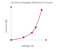
Electronic loads have many functions,such as low-voltage operation, combined operating modes, remote-control interfaces, time-dependent settings, measurement functions and more. There are too many to list here, but it is important to consider which functions will be useful for an application (see Figure 1).

The operating range of electronic loads is often given in terms of power, current and voltage. If our application requires a larger capacity than an electronic load offers, it will not be worth considering. However, if an electronic load has a capacity that is much larger than our application it may be a waste of resources. In addition to the unnecessary cost and size of an electronic load, a larger capacity may mean poorer performance. It is often the case that the higher the rating, the worse the setting accuracy, setting resolution and response is for lower range applications.
A Tale of Two Loads
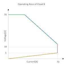
Let’s use an example of load A and B, which have similar but different operating specifications. A is rated at 50 amps, at an operating voltage range from 5~50 V, minimum 2 V, with a power rating of 1,000 W. B is a 70-A, 70-V, 10~70 V (5 V min) device rated at 1,000 W. At first glance B looks better than A. The figures below illustrate the operating area of each electronic load (Figures 2 & 3).
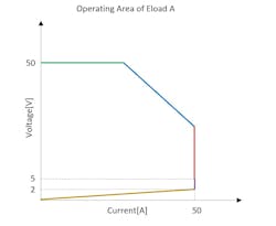
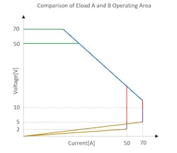
It is important to know what operating area will be needed for your application. Choosing an electronic load with a capacity that is not much larger than what your capacity requires may save you from having to pay unnecessary costs. Let us compare the operating areas of Load A and B.
In the range of 30-40V neither load has the advantage, because both loads have the same power rating. However, load A may be a better choice than B if we need to use lower voltages, because load A has a larger current range for lower voltages, shown by the yellow line. Even though more capacity might be appealing it often comes with more cost. If our application will not require more capacity than load A offers it is unlikely that load B’s larger capacity will offer any advantages. In addition, the higher capacity of load B could result in less resolution and accuracy in measurements and settings.
Power Consumption Methods
As mentioned earlier, electronic loads employ 2 types of power consumption methods, each with their advantages and disadvantages. The Linear regulator type tends to have a faster response, because it employs a linear amplifier, which has a faster response than the switching power devices used in regenerative types. The absence of switching devices also leads to linear regulators having lower noise. Another advantage of a linear electronic load is the ability to use common single-phase 120/240 Vac as input power, even for large-capacity loads (20kW or higher).
Regenerative types have the advantage of being more efficient and operating at lower temperatures. The regenerative type uses switching elements to redirect power back to the grid, offering better efficiency but also slower response, with introduced noise. For the regenerative type to put energy back on to the grid, they require 3 phase and higher-voltage AC connections, which may be a limited resource in a lab.
The regenerative type also operates at a lower temperature than the linear type because energy isn’t dissipated as heat, saving on costs from air conditioning in the lab. When choosing between the different types of power consumption, one should also consider the facilities available in the lab, as well as energy costs and application requirements.
Functionality
As mentioned earlier, the menu of electronic load functions available these days is long, and it’s not possible to explain them in detail here. It is good practice to read manufacturer datasheets to find the functions most relevant to your application. If your application requires an electronic load with special functions, it is recommended you check with the manufacturer to be sure the needs of your application will be satisfied. Datasheets and user manuals are helpful to understand the basics of a function, but they cannot explain all the limitations you may experience in practice. If possible, request to demo the load before purchasing.
Response
Other specifications of electronic loads we need to consider before purchasing are the slew rate, CR response, and CV response. With regards to the slew rate, what often concerns us is the difference between the ideal slew rate and the actual slew rate. When electronic load suppliers list specifications in their catalog or specifications manual the slew rate value is often written as an ideal value.
When we use the load for our application, we may find that it is not the same as the specification. The main reason for this is that the slew rate is not a constant value but changes depending on the current amplitude. For a larger current we can expect a faster slew rate. If an application requires a smaller current amplitude the slew rate will be slower than ideal value given in the specifications.
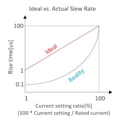
Figure 5 shows an example, using an electronic load with a 100 µs rise time specification when the CC setting is 100% of the current rating. Ideally, the rise time is 100 µs when the setting value is 100%, and the rise time is 1us when the setting value is 1%. But in reality, the slew rate does not change linearly with respect to the current setting. Figure 5 shows a representation of slew rate and current setting as a percent of the max setting, where the blue line represents the ideal case and the red line represents a realistic case.
When the rise and fall time of our electronic load is important to our application it is important to find out the limitations of the slew rate within the current range we will be using the electronic load and when the load is being used make sure the appropriate range setting is being used to get the fastest slew rate possible.
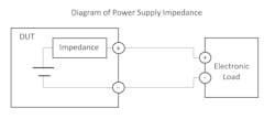
We also need to understand the importance of slew rate in an application. It's important to have a fast slew rate because it helps discover the impedance that a DUT has. An ideal constant voltage source has zero impedance however, real constant voltage sources do have an output impedance which affects the DUT transient response. For example, Figure 6 shows the DUT and electronic load connected.
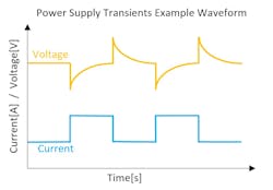
If the electronic load is switching CC level, the waveform will be like the figure below, where the blue line represents the CC level of the load and the yellow line represents the DUT output voltage. As the current rises the voltage level drops by the inductance of the DUT. Next, the DUT tries to restore the output voltage by feedback control and regain the CV setting. When an electronic load with a fast rise/fall time is used with large current fluctuations it allows the user to observe the transient voltage fluctuations and the associated impedance of the DUT (Figure 7).
Incidentally, when a large voltage drop is caused by a DUT’s impedance it can sometimes cause malfunction of DC electronic load because the voltage will drop below the operating area of the load and it will be unable to sink current. If we are testing a DUT that we suspect to have voltage drops we should make sure that it will not be below the operating area of the electronic load. We can also look for loads made with built in bias power supplies that are designed to sink current at low or even 0 V.
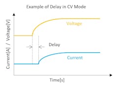
In regards to CR response, the load current swing lags the voltage swing because of the feedback control in the electronic load. The lag is different for each electronic load. If we need a fast CR response, we should check the CR response listed in the manufacturers specifications and ask suppliers for information on the response within the range we plan to use (Figure 8).
When considering the CV response, the most important thing to be careful of is oscillation. The CV mode is achieved by using feedback control that includes the wire’s impedance and DUT’s impedance. Since the point at which oscillation occurs differs depending on the test environment, suppliers have a difficult time accurately listing the response specification in their catalog. However, when we don’t need a fast response, it is possible to use loop gain by connecting a large capacitor to the electronic load terminal to make the response slower and prevent oscillation.
Expanding Operating Area
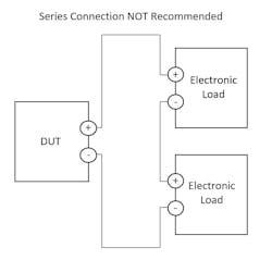
Another important thing to understand when purchasing electronic loads is how multiple units can be connected to expand the capacity. If you have experience using power supplies you may be used to connecting them in series or parallel to expand respectively the operating voltage or current range. It is not as straightforward with electronic loads.
Electronic loads cannot be connected in series to expand the voltage capacity because of the methods electronic loads use to control current to achieve the CC/CR/CV/CP operating modes. If two loads are connected in series it will cause erratic operation such as oscillation, corruption, and test failure. If an application needs a higher voltage it is necessary to purchase an electronic load with a larger voltage operating area (Figure 9).
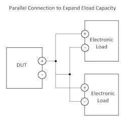
If there is an application that requires a larger operating current it is possible to connect electronic loads in parallel to expand their current capacity. When considering electronic loads for a new application find out the parallel connection capacity of the load. It may be necessary to purchase several units that meet the voltage requirement and connect them in parallel to meet the current requirements of the application (Figure 10).
Looking Forward
From the examples shown above we have seen that electronic loads in the market today have a wide range of functions that make testing DUT’s more efficient and more effective. The capabilities of electronic loads allow them to be used in more demanding applications, but it also makes it more difficult for manufacturers to accurately represent the limitations of their products within the specification documentation.
As a buyer it is important to consider how an electronic load will meet the demands of your application and how easily it can be integrated into your lab as well as the operational costs of using the load. It is a good idea to use the manufacturers specification to narrow your search and then request to demo the remaining devices so you can be sure the load you choose will be suitable for your application.
About the Author
Tomoaki Mori
Kikusui America
Comment About the Article
To join the conversation, and become an exclusive member of Electronic Design, create an account today!

Leaders relevant to this article: