What’s the Difference Between EMI and EMC in Electronic Designs?
This article is part of the TechXchange: Delving into EMI, EMC and Noise.
Members can download this article in PDF format.
What you'll learn:
- What is EMI and what types of EMI exist?
- What is EMC and what are its main features?
- A look at EMI detector design.
- The role of a quasi-peak detector in EMC.
It’s incumbent on electrical/electronic designers and troubleshooters to understand the difference between electromagnetic interference (EMI) and electromagnetic compatibility (EMC).
EMI is caused by electromagnetic emissions that may disturb the function of electronic devices and radio-frequency (RF) systems. Such devices and systems must be properly shielded from electromagnetic radiation for them to perform optimally. EMC measures how well these devices and systems can perform in the presence of any disruptive EMI.
Defining EMI and EMC
EMI definition1
EMI is typically present as undesirable noise in any electrical/electronic system. EMI occurs due to electromagnetic emissions that disturb functionality in radio-frequency (RF) or electronic devices. One way to protect the optimum functionality of systems and devices is the use of proper shielding from electromagnetic radiation. EMC will measure how these devices/systems will function properly in a disrupting EMI environment.
Essentially, EMI is undesirable noise in a system that disrupts electronic, electrical, and RF systems.
There are four kinds of EMI:
- Conducted EMI: This type of EMI, which flows through wires, occurs via physical contact with the source of that EMI.
- Differential-mode EMI: This low-frequency EMI will flow in an opposite direction through adjacent wiring.
- Common-mode EMI: This high-frequency form of EMI flows in the same direction through one or more electrical conductors.
- Radiated EMI: This is the most common type of EMI. It’s caused by radiating electromagnetic fields. Common signs of radiated EMI include “snow” on TV monitors and static noise on AM/FM radio receivers.
EMC definition1
EMC of an electrical, electronic, or RF device has two features:
- The capability of working properly while in the presence of electromagnetic radiation.
- The capability to not generate any additional EMI that may affect the proper operation of any other devices nearby.
The EMC of any device may be improved by using a clever design and shielding, along with EMI filtering. A device’s EMC can be measured via compliance testing by using a dedicated test system that’s composed of antennas, near-field probes, and spectrum analyzers.
EMC testing may prove to be expensive. However, it’s essential to ensure that an electrical/electronic design will function as expected and will not generate disruptive EMI.
EMI and EMC Compliance
EMI and EMC compliance standards are not uniform worldwide. Myriad different regulatory bodies worldwide will each have their own specific standards.
An example is the compliance standards in the European Union (EU) that differ from those in the United States. To further complicate matters, the U.S. military employs far more strict standards than do commercial industries. Commercial compliance standards will often vary depending on the specific industry and the end use of any device.
EMI Detector Design
All electrical/electronic/programmable electronic (E/E/PE) devices can generate, and may also be vulnerable to, electromagnetic disturbances (EMD). EMD may create critical errors in an electronic system.
A correct and safe operation can be achieved via increasing demand for safety- and mission-critical systems. A combined expertise in the engineering disciplines of EMC, risk management, and functional safety have become quite important.
The IEEE Standard 1848-2020 focuses on measurements and techniques that could be used to make a system quite resilient to EMI via design.
Wired communication channels still play a critical role in modern-day communication systems. It’s key for designers to focus on their dependability. Many hardware- and software-based methods are designed to render a wired communication channel to be EMI-resilient via proper design.
Some hardware-based techniques involve detection of EMI and frequency, spatial and time diversity. There are also software-based approaches that include error detection codes (EDCs) and error correction codes (ECCs). The key goal of these techniques and measures is to be able to detect and correct EMI-related bit errors in the communication channel.2
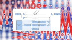
A Field Probe Adder Subtractor (FPAS) EMI detector was proposed in Reference 3 (see figure). This method can detect the EMD induced in a wired communication channel.
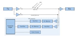
This kind of detector is used at the receiver end and will generate a warning when an EMD disrupts the data transmitted. This type of warning may be used by the system to request a retransmission of data or shift the system into a safe state. The Adder & Subtractor (A&S) EMI detector can’t detect EMI at those EMI frequencies, which are an integer multiple of the detector sampling rate.
Field probes are able to characterize the electromagnetic (EM) environment and detect the EMD. One problem with these types of probes is that conventional field probes are slow and costly. A possible remedy for this is the received signal strength indication (RSSI)-based fast probes that can operate as an EMI detector.
Such probes will produce dc output voltages that are able to be used for measuring the field envelope. They have a flat frequency response along with an improved sensitivity at low frequencies, enabling them to readily detect EMI in a harsh EM environment.
The FP EMI detector will generate a large number of data false positives (DFPs), which in some cases compromises the detector availability. However, the FPAS EMI detector can overcome this limitation with the A&S EMI detector that implements the Field Probe (FP) EMI detector. However, the FPAS EMI detector will continue to produce a limited number of DFPs. Studies are ongoing to reduce DFPs.
EMC Quasi-Peak Detector
Quasi-peak detectors (QPDs) are a weighted form of peak detection.4 The measured value of the QPD falls as the repetition rate of the measured signal increases. QPD is a method of measuring the “annoyance factor” of a signal. This is just like listening to a radio, where every couple of seconds you hear a “pop” related to noise.
A majority of conducted and radiated limits in EMC testing are based on the quasi-peak detection mode. A quasi-peak detector will weigh signals according to their repetition rate. This is a method of measuring their "annoyance factor." This is achieved by having a charge rate that’s much faster than the discharge rate. So, as the repetition rate ramps up, the QPD will not have enough time to discharge as often, leading to a higher voltage output (i.e., response to a spectrum analyzer).
For continuous-wave (CW) signals, the quasi-peak and peak responses will be the same. In addition, a quasi-peak detector will also respond, in a linear manner, to different amplitudes. Low-repetition-rate, high-amplitude signals can produce the same output as low-amplitude, high-repetition-rate signals.
During measurement, QPD readings will always be less than or equal to peak detection. Quasi-peak readings are far slower (by two or three orders of magnitude as compared with peak). It’s quite common to initially scan using peak detection, and then, if that is only marginal or fails, to switch and run the quasi-peak measurement against the limits.
Summary
EMI isn’t a desirable phenomenon, and EMC is a set of practices and rules that will control it. Without EMI, EMC isn’t necessary; without EMC, EMI will ultimately cause design problems.
Read more articles in the TechXchange: Delving into EMI, EMC and Noise.
References
1. "EMI vs. EMC: What’s the Difference?," Captor Corporation, 2020.
2. "Combining Fast Field Probes with an EMI Detector to reveal Bit Errors induced by ElectroMagnetic Disturbances", Proc. of the 2022 International Symposium on Electromagnetic Compatibility (EMC Europe 2022), Gothenburg, Sweden, September 5-8, 2022.
3. H. Habib, T. Claeys, D. Vanoost, and G. A. E. Vandenbosch, and D. Pissoort, “Development of an EMI detector based on an inverted data pair with reduced number of false negatives,” 2020 International Symposium on Electromagnetic Compatibility (EMC Europe 2020).
4. “What is Quasi-peak Detection?,” Keysight Technologies.
About the Author

Steve Taranovich
Freelance Technical Writer, Phoenix Information Communication LLC
Steve is a contributing editor to Electronic Design.
Author of the non-fiction “Guardians of the Right Stuff,” a true story of the Apollo program as told by NASA and Grumman Corp. engineers, an astronaut, and technicians.
Experienced Editor-In-Chief of EETimes/Planet Analog and Senior Technical Editor at EDN running the Analog and Power Management Design Centers from 2012 to 2019.
A demonstrated history in electronic circuit design and applications for 40 years, and nine years of technical writing and editing in industry. Skilled in Analog Electronics, Space-related Electronics, Audio, RF & Communications, Power Management, Electrical Engineering, and Integrated Circuits (IC).
1972 to 1988 worked as a circuit design engineer in audio (8 years) and microwave (8 years). Then was Corporate Account Manager/applications engineer for Burr-Brown from 1988 to 2000 when TI purchased Burr-Brown. Worked for TI from 2000 to 2011.
Strong media and communication professional with a BEEE from NYU Engineering in 1972 and an MSEE from Polytechnic University in 1989. Senior Lifetime member of IEEE. Former IEEE Long Island, NY Director of Educational Activities. Eta Kappa Nu EE honor society member since 1970.
Comment About the Article
To join the conversation, and become an exclusive member of Electronic Design, create an account today!

Leaders relevant to this article: