SiC E-Fuse Demonstrator Speeds Evaluation for EV Apps

This article is part of the TechXchange: Silicon Carbide (SiC).
You have to feel some empathy for the classic thermally activated fuse, which has faithfully served electrical engineers at all power levels for well over a hundred years. Despite its virtues—and there are many—it has been supplemented, supplanted, and even superseded in many cases by the electronic fuse, or e-fuse. Putting nostalgic feelings aside, there’s no arguing the many benefits of the e-fuse: adjustability, resettability, flexibility, and remote, I/O-based setting and readback, to cite a few.
Billions of thermal fuses are still used annually, and there’s also no denying that the operating and functional simplicity of the thermal fuse is also a virtue in its own way. Look at it this way: Once you select the desired type and rating, there’s nothing more to do to make it operational—no initialization, no settings; you just install it and it’s ready to function. It’s the passive-component equivalent of “plug and play.”
The scenario different for e-fuses, and this is the challenge addressed by the E-Fuse Demonstrator Board from Microchip Technology Inc., enabled by the company’s 700- and 1,200-V silicon-carbide (SiC) technology (Fig. 1).
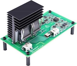
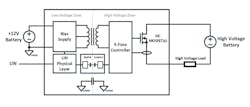
It gives designers of pure battery and hybrid electric vehicles (BEVs and HEVs) a faster and more reliable high-voltage circuit-protection solution. The board is available in six variants for 400- to 800-V battery systems, with current ratings of 10, 20, and 30 A (Fig. 2). Note that the hardware design uses only AEC-qualified components for compatibility with automotive bill-of-materials requirements and technical mandates.
Due to its high-voltage solid-state design, the E-Fuse Demonstrator can detect and interrupt fault currents in 10 µs, which is far faster than the traditional approaches. This fast response time substantially reduces peak short-circuit currents from tens of kiloamps down to hundreds of amps, and thus can prevent a fault event from resulting in a hard failure.
With the E-Fuse Demonstrator’s resettable feature, designers can easily package an e-fuse in the vehicle without the burden of design-for-serviceability constraints. This reduces design complexities and enables flexible vehicle packaging to improve BEV/HEV power system distribution.
Furthermore, the E-Fuse Demonstrator accelerates development of SiC-based auxiliary applications due to its built-in Local Interconnect Network (LIN) communication interface. This interface enables the configuration of the overcurrent trip characteristics without the need to modify hardware components, and it reports diagnostic status.
Low-voltage operating range is 9 to 16 V, while the high-voltage operating range is 200 to 900 V. This design also implements a time-current characteristic (TCC) curve that helps designers migrate to non-automotive applications such as dc solid-state circuit breakers.
Full details on the Demonstrator are provided by the 74-page High-Voltage Auxiliary E-Fuse User’s Guide. This is supplemented by the MPLAB X integrated development environment (IDE), which enables designers to quickly develop or debug software, while the LIN Serial Analyzer development tool allows them to easily send and receive serial messages from a PC to the E-Fuse Demonstrator Board.
Read more articles in the TechXchange: Silicon Carbide (SiC).
About the Author

Bill Schweber
Contributing Editor
Bill Schweber is an electronics engineer who has written three textbooks on electronic communications systems, as well as hundreds of technical articles, opinion columns, and product features. In past roles, he worked as a technical website manager for multiple topic-specific sites for EE Times, as well as both the Executive Editor and Analog Editor at EDN.
At Analog Devices Inc., Bill was in marketing communications (public relations). As a result, he has been on both sides of the technical PR function, presenting company products, stories, and messages to the media and also as the recipient of these.
Prior to the MarCom role at Analog, Bill was associate editor of their respected technical journal and worked in their product marketing and applications engineering groups. Before those roles, he was at Instron Corp., doing hands-on analog- and power-circuit design and systems integration for materials-testing machine controls.
Bill has an MSEE (Univ. of Mass) and BSEE (Columbia Univ.), is a Registered Professional Engineer, and holds an Advanced Class amateur radio license. He has also planned, written, and presented online courses on a variety of engineering topics, including MOSFET basics, ADC selection, and driving LEDs.
Comment About the Article
To join the conversation, and become an exclusive member of Electronic Design, create an account today!

Leaders relevant to this article: