CISPR 25 Class 5: Evaluating EMI in Automotive Applications
This article is part of the TechXchange: Delving into EMI, EMC and Noise.
Members can download this article in PDF format.
What you'll learn:
- Methods for CISPR 25 conducted emissions testing.
- Measurements involved with the current- and voltage-probe test methods.
- A look at a CISPR 25 Class 5 USB Type-C charger reference design.
CISPR 25 is an international standard (Edition 5.0; CISPR 25:2021) that contains limits and procedures to measure radio disturbances within the frequency range of 150 kHz to 2.5 GHz. This standard applies to any electronic or electrical component intended for use in vehicles, trailers, internal combustion engines, boats, and any electronic/electrical component design for use in other such devices.
The standard’s limits are designed to provide protection for receivers, which are installed within an automotive vehicle, from any disturbances made via components or modules within that vehicle. The process and limits for a complete vehicle (even if it’s connected to the power mains for charging purposes or not) and the methods and limits for components or modules are specified in the CISPR 25 standard.
CISPR 25 Current Probe
For the CISPR 25 Current Probe and conducted emissions (CE), the CISPR 25 standard offers two methods for CE testing: the current-probe and voltage-probe methods. Either may be employed to determine if the device under test (DUT) will pass or fail the CE test limits.
Required equipment for the tests include:
- Reference ground plane
- Power supply
- Artificial network
- Load simulator
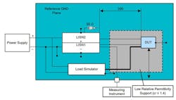
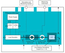
Figures 1 and 2 below outline the physical test setup for the voltage method’s remote ground and the current method’s remote ground, respectively. The complete setup is described in CISPR 25.
Performing CISPR 25 CE Measurements with the Voltage Method
CISPR 25 CE measurements for the voltage-probe method were performed within the frequency range of 0.15 to 108 MHz. In the voltage method’s remote ground test setup, it’s important that the line impedance stabilizer network (LISN2), which isn’t connected to the measuring instrument, is terminated with a 50-Ω load. This impedance match ensures that no reflections will reflect back into the source and that the measurements will be valid.
Figure 1 demonstrates the voltage method. This test will take the measurement directly from the artificial network by connecting one end of the cable to the LISN1 and the other end to the spectrum analyzer.
CISPR 25 CE measurements, for the current probe method, were performed within the frequency range of 0.15 MHz to 245 MHz.
Performing CISPR 25 CE Measurements with the Current Method
In the current-probe method (Fig. 2), the probe must be clamped around the entire wire harness to the DUT, which is then connected to the spectrum analyzer to take the measurement.
The artificial network, a.k.a. LISN, is located directly upon the reference ground plane shown in Figures 1 and 2. The LISN serves to stabilize the impedance that’s detected via the DUT, which looks at the DC battery, and blocks any external noise that may appear on the power cables.
The two separate LISNs are connected to the negative (−) and positive (+) terminals of the battery—LISN1 to the (−) and LISN2 to the (+).
We need to note that CISPR 25 conducted emission levels for the current and voltage methods were selected to have almost equal limit lines. In the simulations, it was shown that at low frequencies, the impedance of the 5-μH inductor in the LISN network will allow for some current to flow through it instead of flowing through the 50-Ω resistor. This will result in the voltage method having limits below 5 MHz. Both methods are widely used, and it’s crucial that designers understand how they compare to each other.
The following section will outline an automotive charger reference design example that meets the CISPR 25 Class-5 conducted EMI standards.
Real-World Application: USB Type-C Charger Reference Design
This reference design is EMI-optimized for automotive USB Type-C chargers with dual 15-W outputs.3 Texas Instruments’ TPS25850-Q1 is used as a DC-DC regulator and port controller. Switching frequency is 2.2 MHz. The front-end filter is well-designed, and the PCB layout is optimized to meet the stringent CISPR 25 Class-5 conducted electromagnetic interference (EMI) standards. Check out this video:
This reference design has been tested to CISPR 25 Class 5 conducted EMI standards, which will help accelerate customer design time.
USB Type-C eliminates the need for different plug and receptacle types for host and device functionality. The Type-C receptacle displaces both the Type-A and Type-B receptacles since the Type-C cable is pluggable in either direction between the device and host.
Every USB Type-C port will be able to operate in one of following data modes:
- Host mode: The port can only be a host (i.e., a provider of power).
- Device mode: The port can only be a device (i.e., a consumer of power).
- Dual-role mode: The port can be either a host or device.
Texas Instruments has another similar reference design: “Isolated 5V bias supply for automotive CISPR 25, class 5 emissions.”
Read more articles in the TechXchange: Delving into EMI, EMC and Noise.
References
1. “An overview of conducted EMI specifications for power supplies,” Timothy Hegarty, Texas Instruments.
2. “Understanding CISPR 25 Current Probe and Voltage Method for Conducted Emissions,” Madison Eaker, Delaney Berger, Texas Instruments.
3. “Test Report: PMP40723 CISPR 25 Class-5 2.2-MHz Rated 30-W Automotive Dual USB Type-C® Charger Reference Design,” Texas Instruments, 2021.
4. CISPR 25 Edition 5.0, Testups
5. PMP9398 reference design: “CISPR 25 Class 5 Rated 6.6W Automotive Power Reference Design.”
6. PMP9397 reference design: “CISPR 25 Class 5 Rated 3.3W Automotive Power Reference Design.”
7. PMP9481 CISPR 25 Class 5, 3-W SEPIC reference design for automotive infotainment display power.
8. CISPR 25: Automotive Component EMC Testing, TUV Accredited Testing Laboratory.
9. “Meet CISPR 25 Class 5 EMI standards with fully integrated isolated DC/DC module,” YouTube.
10. “UCC12051-Q1, Automotive, 500-mW, 5-kVrms isolated DC/DC module with integrated transformer,” Texas Instruments.
11. “A review of EMI standards, part 1 – conducted emissions.”
12. “A review of EMI standards, part 2 – radiated emissions.”
About the Author

Steve Taranovich
Freelance Technical Writer, Phoenix Information Communication LLC
Steve is a contributing editor to Electronic Design.
Author of the non-fiction “Guardians of the Right Stuff,” a true story of the Apollo program as told by NASA and Grumman Corp. engineers, an astronaut, and technicians.
Experienced Editor-In-Chief of EETimes/Planet Analog and Senior Technical Editor at EDN running the Analog and Power Management Design Centers from 2012 to 2019.
A demonstrated history in electronic circuit design and applications for 40 years, and nine years of technical writing and editing in industry. Skilled in Analog Electronics, Space-related Electronics, Audio, RF & Communications, Power Management, Electrical Engineering, and Integrated Circuits (IC).
1972 to 1988 worked as a circuit design engineer in audio (8 years) and microwave (8 years). Then was Corporate Account Manager/applications engineer for Burr-Brown from 1988 to 2000 when TI purchased Burr-Brown. Worked for TI from 2000 to 2011.
Strong media and communication professional with a BEEE from NYU Engineering in 1972 and an MSEE from Polytechnic University in 1989. Senior Lifetime member of IEEE. Former IEEE Long Island, NY Director of Educational Activities. Eta Kappa Nu EE honor society member since 1970.
Comment About the Article
To join the conversation, and become an exclusive member of Electronic Design, create an account today!

Leaders relevant to this article: