11 Myths About Power Distribution

This article appeared in Microwaves & RF and has been published here with permission.
What you’ll learn:
- How to avoid common mistakes made concerning power distribution in connectors and PCBs.
- What rules of thumb are no longer valid?
- Why heat matters so much in PCB power distribution.
As new designs come online with their associated power requirements, designers face new power integrity challenges. Unfortunately, some misconceptions exist about power distribution and some old rules of thumb that need retiring, particularly as they apply to interconnects. What follows are some of the most common myths about power distribution in connectors and PCBs. The bottom line, though, is that power distribution doesn’t have to be a mystery—we need only to pay attention to the relevant details.
1. A connector’s power rating is the same regardless of stack height.
For connectors, the limiting parameter is the self-heating due to the flow of current through it. If you take the current, square it, and multiply by the resistance, you get the power that’s dissipated in the connector. Too much heat will slowly degrade or even destroy the connector. As a result, designers need to carefully consider how high that temperature will rise during operation.
So, does the same current rating apply to different stack heights? No. For each stack height, the resistance of the connector will be different. Therefore, power dissipation will also be different, and the connector will have a different rating. Moreover, heat from the middle of taller connectors can’t escape so easily, further increasing the maximum temperature.
2. The connector’s current rating is the same for vertical and right-angle styles.
This is sometimes true, but not always. If the total pin length is the same between right-angle and vertical, then the current rating will be comparable.
However, if the right-angle configuration has a different length compared to the baseline vertical, it will be different because a pin’s resistance is approximately linearly proportional to its length (it would be exactly linearly proportional if the cross-section of the pin or blade was uniform throughout its entire length). In summary, dissipated power translates to temperature rise, and it can be hugely dependent on construction.
3. Current-carrying capacity testing can be AC or DC.
No, standard current-carrying capacity (CCC) testing is strictly DC. AC current (or a superposition of DC and AC currents) would heat up the connector. Then, we would have to consider the root-mean-square (rms) value of the current, which would depend on several parameters of the AC current, making it harder to specify a limit in simple terms. For more information, check out “Simplified Pulse Current Duty Cycle Guidelines.”
4. DC penetrates the connector cross-section uniformly.
It’s often thought that DC penetrates conductor cross-sections uniformly. But it doesn’t necessarily, unless we enforce strict, often impractical, conditions. This misconception often comes from using a typical textbook calculation of resistance that assumes current penetrates a cross-section uniformly and doesn’t change along the lengths.
That assumption breaks down when a conductor’s aspect ratio isn’t long and skinny, but rather it’s thicker (like a power-connector blade). One can’t assume that the current penetrates a cross-section uniformly, because it very much depends on the conductor geometry around the connector. The actual current distribution can’t be answered without knowing the circuit characteristics.
The good news is that if you perform a DC simulation with any of today’s professional simulators, you will get the correct answer. There’s a bigger risk if you do not.
5. Surface roughness is only a concern for high frequencies.
The impact of surface roughness is very hard to prove through measurements. But engineers have known the impact of surface roughness at high frequencies for decades, and the industry has come to a consensus on how to describe and capture its impact. It’s hard to simulate at high frequencies, and such simulations must be done iteratively with detailed knowledge of the surface topology so that we can accurately set the parameters of the simulation.
You can’t use these same simulations at low frequencies. It would require meshing of the exact surface topology, which isn’t a practical task. This mostly applies to PCBs, but connector contacts aren’t perfectly smooth either (it’s easier to determine the surface topology of connectors pins or blades; a PCB’s conductor layers are obscured). Moreover, even if you know the roughness of the copper sheet before it’s laminated within the PCB, the processing steps change the roughness.
The bottom line: Surface roughness is a problem not only at high frequencies but is also a potential problem for DC. It’s just much harder to put a number on it.
6. Lowering PDN impedance on the PCB will reduce noise.
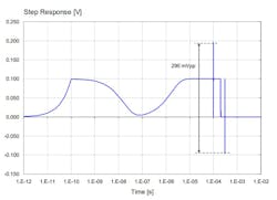
Since the early 1990s, a favored means of designing a power-distribution network (PDN) has been with reference to its impedance. The misconception: Lowering the impedance in any frequency range will lower the noise.
What really matters for worst-case transient noise is the impedance value together with flatness. Flatness (how much the frequency response fluctuates), for example, is a significant contributor to the worst-case transient noise (Fig. 1). For more information, check out “Systematic Estimation of Worst-Case PDN Noise” and “How to Design a PDN for Worst Case?”
7. Temperature limits are meant to protect the connector contact.
Temperature limits are determined by what fails first. In the case of connectors, it’s widely believed that limiting the temperature they see is on behalf of the contact. Connector contacts are typically a composite layered material, often copper with nickel and gold plating. With such materials, it’s important to understand that there’s a temperature limit before some degradation occurs.
But the plastic used in connectors may have a limit as well, and it could be lower than the contact (especially if the connector is manufactured using low-cost nylon). If that limit is reached, the connector’s plastic housing degrades and becomes soft, which in turn degrades the precision of the blade/pin position.
Typically, this isn’t a concern if the connector’s body is composed of a liquid crystal polymer (LCP). Then, the temperature limitations are usually set depending on the type of plating on the contact.
8. Inductors aren’t good for PDNs.
An old maxim holds that “if I purposefully design in a component, such as a series inductor, that cannot be good for the PDN under any circumstances.” In fact, situations arise where series filtering is very useful, such as using an inductor to filter out noise from noisy loads like a DC-DC converter. There’s much more detail on this here: Using Ferrites and Inductors in Power Distribution Networks (PDN).
9. X5R capacitors are worse than X7R for DC bias.
This was true 30 to 40 years ago, but in general, it’s not the case today. Now, it really depends on the material and manufacturing process details of the multi-layer ceramic capacitor. Use a verified vendor’s datasheet or measure it directly. More detail on this can be found in a talk titled “Multi-layer Capacitor (MLCC) Losses” and also here: “DC Bias Effect in Ceramic Capacitors.”
10. Small-value capacitors are better for high frequencies.
This is a very widely held misconception because decades ago it was true. As frequency goes up, inductive reactance goes up, too, so lower inductance helps. The physical size of the capacitor affects its inductance (with a smaller capacitor, we expect lower inductance).
In the past, a 1-nF capacitor was much smaller than a 100-nF part. However, dielectric materials and manufacturing processes have evolved to the point where we can get a very wide range of capacitance values in the same-size package. Of course, the inductance still depends on the size of the capacitor, but not necessarily on its capacitance value.
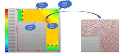
11. Right-angle turns hurt only high-frequency or high-speed signals.
The truth is that current crowds at sharp corners and, thus, resistance increases for all types of signals, whether at low or high frequency. The current density isn’t uniform at the right-angle turn (almost 5X at the inner corner in Figure 2), which can cause discontinuity and perhaps result in overheating. The better approach is to make an arc, just like at high frequencies. For more information, see “Perils of RA Turns at DC.”
About the Author
Istvan Novak
Principal Signal and Power Integrity Engineer, Samtec
Istvan Novak is a Principal Signal and Power Integrity Engineer at Samtec, working on advanced signal- and power-integrity designs. Before 2018, he was a Distinguished Engineer at SUN Microsystems (later Oracle). He worked on new technology development, advanced power distribution, and signal-integrity design and validation methodologies for SUN’s workgroup server families.
Novak introduced the industry's first 25-μm power-ground laminates for large rigid computer boards and worked with component vendors to create a series of low inductance and controlled-ESR bypass capacitors. He also served as SUN’s representative on the Copper Cable and Connector Workgroup of InfiniBand and was engaged in the methodologies, designs, and characterization of power-distribution networks from silicon to DC-DC converters.
Novak is a Life Fellow of the IEEE with 29 patents to his name. He’s also the author of two books on power integrity, teaches signal- and power-integrity courses, and maintains a popular SI/PI website. Istvan was named Engineer of the Year at DesignCon 2020.
Comment About the Article
To join the conversation, and become an exclusive member of Electronic Design, create an account today!

Leaders relevant to this article: