How to Reduce Harmonics in Power-System Design

This article is part of the TechXchanges: Delving into EMI, EMC and Noise and Power Supply Design.
Members can download this article in PDF format.
What you’ll learn:
- How to measure harmonics in a power system.
- Methodologies for reducing power system harmonics.
- A look at "triplen" harmonics.
The IEEE standard 3002.8-2018, “Recommended Practice for Conducting Harmonic Analysis Studies of Industrial and Commercial Power Systems,” addresses the requirements for performing power-system harmonic analysis studies in industrial and commercial power systems due to increasing load nonlinearities and control devices.
What follows are ways to measure and reduce or eliminate the problems caused by harmonics.
Successfully Measuring Power-System Harmonics
Harmonic analysis is a discipline that’s quite different from any traditional methods used to solve problems in power systems. Finding solutions once a system is at the power system frequency will not do the job, though. The harmonic problem must be solved at multiple frequencies.
It’s critical to understand this distortion by measuring it on both the voltage and current levels for the power system. The power system will have a hardware interface; advanced software that can measure, analyze, and report the harmonic conditions of the power system; and lastly a PC.
Maximizing the efficiency and reliability of power networks can be achieved by increasing the power quality of the system. Harmonic content is a prime cause of low power quality. Agency standards help to ensure that manufacturers follow guidelines to measure and control harmonics.
To measure harmonics, engineers and technicians can use a clamp meter that indicates total harmonic distortion (THD) levels. The THD for voltage should not exceed 5% in most cases, while the THD for current will run much higher. Alternatively, testing the design with a power-quality analyzer can be performed to investigate the effects and magnitude of individual harmonics.
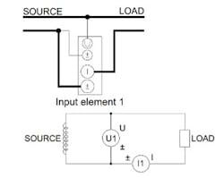
A power-analysis instrument is also a good option for measuring and controlling harmonic disturbances (see the appropriate “Getting Started” guide, in Reference 5, for an instrument’s wiring instructions) (see figure). The essential task at hand is to analyze the specific source and generation mechanism of the system harmonics. It’s only then that designers will be able to propose an optimization method for phase-shifting control that will suppress the harmonics.
Reducing Harmonics
There are multiple ways to reduce and/or eliminate harmonics in system design:
Harmonic mitigating transformers
K-rated transformers, which comply with ANSI’s definition of K-factor, are designed to withstand any overheating problems that are created by harmonics. The use of a harmonic mitigating transformer will help to mitigate problems by reducing or even canceling harmonics.
So, what’s K-factor? The ANSI Standard C57.110-1986 defines it as a metric for evaluating the level of harmonic current that a circuit draws and determining the heating effect of that harmonic current.
In systems affected by harmonics, the K-factor can be measured with a power-quality analyzer. A K-factor of 1 will indicate a linear load. A higher K-factor will indicate an increase in heating from those harmonics. An example would be a circuit with a K-factor of 2, which will have twice the heating effect of a circuit with a K-factor of 1.
Manufacturers that submit their transformers to be evaluated by Underwriters Laboratories (UL) for harmonic loads can apply the UL label: "Suitable for Non-Sinusoidal Current Load with K-Factor not to exceed 4, 13, 20, 30, 40, or 50." However, loads with K-factors higher than 20 are rare.
Harmonic filters
Harmonic filters may be designed into a system to reduce harmonics. Designers may consider Installing harmonic filters to reduce the harmonic distortion levels and shift resonance frequencies to less harmful regions.
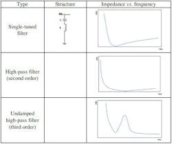
Harmonic filtering that employs passive filters is one of the easiest and most practical methods for harmonic distortion reduction, along with parallel resonance mitigation.
The table shows commonly used filters, along with their impedance magnitude versus frequency characteristics.
Methods for Mitigating VFD Harmonics
Nonlinear devices are increasingly being used in industry, which will ultimately lead to expensive production interruptions as well as electrical facility malfunctions.
THD and harmonic levels must be measured at the point of common coupling (PCC). When troubleshooting this kind of system, the PCC is the point at which the nonlinear loads typically become problematic and will be connected to the rest of the distribution system.
A variable-frequency drive (VFD), or adjustable-frequency drives, adjustable-speed drives, variable-speed drives, AC drives, micro drives, and inverter drives are kinds of AC motor drives (in a system incorporating a motor) that can control the torque and speed by varying the input frequency of the electricity.
VFDs are usually employed in applications that can range from small appliances to large compressors. Systems with VFDs may have a higher efficiency than hydraulic systems (for example, systems with damper controls and pumps used in many fans).
VFDs are susceptible to electrical harmonic distortion problems. Harmonics can be any current form at an integral multiple of the fundamental frequency. For example, it’s usually 50 Hz for three-phase AC power in China. Harmonics may cause problems in electrical systems, so it’s very important to understand how those harmonics are generated and the circumstances for which the harmonics may be harmful to a system.
Many different methods can be applied to reduce, or even, eliminate the harmonic content created by a VFD. One simple method is to add an inductor to the input of the VFD. This inexpensive solution will help reduce harmonic content from higher than 60% down to the 40% range.
Designers can also use harmonic mitigating transformers to reduce power-system harmonics. Transformers configured with Delta-Wye wiring can aid in lowering harmonic effects, too.
What are Triplen Harmonics?
Triplen harmonics (or triplens) are defined as odd multiples of third-order harmonics (3rd, 9th, 15th, etc.). Only single-phase loads will generate triplen harmonics.
Triplen harmonics may lead to problems such as overloading in neutral conductors, transformer overheating, as well as telephone interference. Three-phase electronic loads that are connected phase-to-phase—for example, 208-V power supplies or 480-V variable-speed motor drives—will not generate any triplen harmonics. However, these three-phase electronic loads are able to generate high levels of other higher-level harmonics.
Single-phase electronic loads connected in a phase-to-neutral configuration, as in 120-V office circuitry and 277-V lighting circuitry, will generate third harmonic distortion along with deceasing levels of higher odd harmonics.
Summary
This article offers tips and methodologies on measuring and reducing, or even eliminating, harmonics in power systems. The use of K-rated transformers will help to mitigate system harmonics, and harmonic filters can be used to lower or virtually eliminate distortion.
Ultimately, measuring the system harmonics will enable designers to determine the right level of harmonics that can be tolerated in a power-system design to meet the overall final target of system performance.
Read more articles in the TechXchanges: Delving into EMI, EMC and Noise and Power Supply Design.
References
1. “Ability of Detuned Reactors and Harmonic Filters to Improve Power Quality in Hybrid AC/DC Power Systems,” 2022 5th International Seminar on Research of Information Technology and Intelligent Systems (ISRITI).
2. “Guide to Transformer Harmonics and K-Factor,” Maddox
3. “Industrial and Commercial Power System Harmonic Studies: Introduction to IEEE Std. 3002.8 – 2018,” JJ Dai, PhD, SIEEE, Department of Energy and Farrokh Shokooh, PhD, LFIEEE, etap.
4. “A Measurement Technique for Power System Harmonics,” C. Gilker, D. G. Flinn, 1990.
5. “How to Make Successful Harmonic Measurements,” Yokogawa, 2021.
6. “Dynamic Harmonic Analysis of Power Router with Common High-frequency AC Bus Based on Phase Shift Control,” The 6th IEEE International Conference on Predictive Control of Electrical Drives and Power Electronics, IEEE 2021.
7. “A New Method for Power Factor Correction and Harmonic Elimination in Power Systems,” I. Kasikci, MIEEE, VDE, 2000, IEEE.
8. “Distributed Carrier Phase Shifting Control Method for Modular Interleaved Parallel Inverters,” IEEE Transactions on Transportation Electrification, Vol. 9, No. 2, June 2023.
About the Author

Steve Taranovich
Freelance Technical Writer, Phoenix Information Communication LLC
Steve is a contributing editor to Electronic Design.
Author of the non-fiction “Guardians of the Right Stuff,” a true story of the Apollo program as told by NASA and Grumman Corp. engineers, an astronaut, and technicians.
Experienced Editor-In-Chief of EETimes/Planet Analog and Senior Technical Editor at EDN running the Analog and Power Management Design Centers from 2012 to 2019.
A demonstrated history in electronic circuit design and applications for 40 years, and nine years of technical writing and editing in industry. Skilled in Analog Electronics, Space-related Electronics, Audio, RF & Communications, Power Management, Electrical Engineering, and Integrated Circuits (IC).
1972 to 1988 worked as a circuit design engineer in audio (8 years) and microwave (8 years). Then was Corporate Account Manager/applications engineer for Burr-Brown from 1988 to 2000 when TI purchased Burr-Brown. Worked for TI from 2000 to 2011.
Strong media and communication professional with a BEEE from NYU Engineering in 1972 and an MSEE from Polytechnic University in 1989. Senior Lifetime member of IEEE. Former IEEE Long Island, NY Director of Educational Activities. Eta Kappa Nu EE honor society member since 1970.
Comment About the Article
To join the conversation, and become an exclusive member of Electronic Design, create an account today!

Leaders relevant to this article: