Pre-Charge Circuits Lead to Safer EVs
Members can download this article in PDF format.
What you’ll learn:
- What is a pre-charge circuit and what role does it play?
- The fundamental elements of a pre-charge circuit.
- Some basic best practices and where to find more information.
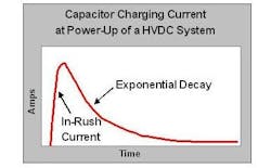
A common challenge in systems operating at higher voltage occurs during initial power-up with so-called “inrush” current, particularly when a significant capacitive load is part of the circuitry (though resistive and inductive issues are also important to consider and understand).
Inrush current has the potential to damage or at least stress components if not managed in some way. This basic situation is common in modern electric vehicles (EVs) that often operate at 400 V, with some now operating at 800 V.
EVs are particularly affected by this problem since they’re often turned off and then on many times each day, repeating the cycle of inrush current. Energy conservation can also dictate depowering when an immediate demand for power isn’t present, requiring yet more reapplications of power.
Pre-Charging Ups the Safety Level in EVs
The standard approach to managing this problem is pre-charging. Its goal is to protect electrical and electronic components from damage and ensuring long, trouble-free service for the vehicle and its systems. By keeping systems functioning as intended, pre-charging has the additional benefit of reducing the likelihood of safety hazards associated with electrical power such as fire or shock.
For example, even arcing due to a fault condition can be reduced by pre-charging. Furthermore, pre-charging can ensure a better diagnostic environment, making it possible to detect problems before they become catastrophic and cause more serious damage. Even protective devices such as circuit breakers can be protected from tripping simply due to the application of power to the system by implementing pre-charging.
Unlike in systems without pre-charging, during a pre-charging process, system voltage rises relatively slowly and in a controlled manner. As voltage rises to reach a steady state, pre-charging is no longer needed. It can be taken out of the circuit, normally through some automatic method. This is usually designed to occur when the main circuit reaches 90% to 95% of the designed operating voltage.
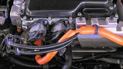
While there are many variations in approach, EV motor controllers often include a capacitor as well as a high-current relay called a contactor that can serve as an emergency disconnect as well as disable the system when not in use. Contactors are vulnerable to arcing and pitting, like old electromechanical “points” in early internal combustion engines, when going through a duty cycle that involves high-voltage battery power.
Pre-charging addresses such a challenge by applying current to the capacitor in the circuit.
In general, the specific concerns that speak to the need for pre-charge include:
- When a fuse is likely to blow due to current inrush.
- When contactors are likely to be damaged by current inrush.
- When battery cells aren’t rated to handle the inrush current.
- When capacitors are likely to be damaged by inrush current.
Pre-Charge Components and Implementation
Parallel and series circuits comprise the pre-charge. Wired in parallel with the main contactor is the pre-charge circuit, usually a smaller contactor in series with a resistor.
The pre-charge circuit usually consists of a separate, smaller contactor connected in series with a resistor. These two components are then wired in parallel with the main contactor, typically along the positive side. The resistor’s role is to make the charging of the capacitor more gradual. Pre-charge resistors run the gamut of technology from ceramic and carbon to extruded aluminum and thin film.
Pre-charge comes in two flavors. Some designers implement relatively complex pre-charging that happens as part of a power-up sequence. When power consumption is less of a concern, the pre-charging is maintained at all times.
More complex systems apply pre-charge as part of the starting sequence and will defer main contactor closure until the pre-charge voltage level is detected as sufficiently high.
Pre-charge components must be rated for the same VOLTAGE as the battery. Current requirements are more complex. Brief peak currents are the more critical issue rather than prolonged current-carrying capacity. Resistors, for instance, must handle peak current and dissipate the most heat energy at the start of the pre-charge process. Finding the right fit means diving into datasheets.
A common and likely point of failure remains the resistor, which can be overheated by frequent cycling or by a failure to reach the intended pre-charge point, causing prolonged or repeated operation. This can be avoided by counting and limiting cycles in a specific period of time or by monitoring and limiting “on” time. And, of course, heat dissipation (heatsinks) can also help address this common point of failure.
In addition to pre-charge circuits using electromechanical contactors, semiconductor-based pre-charge cutoff and current control is starting to appear in smaller two- and three-wheel EVs, where the technology is robust and inexpensive enough to make sense. It seems likely that this technology will eventually appear in larger EVs as well.
References
“Pre-charge systems for lithium-ion battery packs”
“How a high voltage Precharge circuits works on a DIY Tesla drive project”
About the Author

Alan Earls
Contributing Editor
Comment About the Article
To join the conversation, and become an exclusive member of Electronic Design, create an account today!

Leaders relevant to this article: