Move Thermal Issues To The Front Of Your Design Cycle

It’s an old engineering story, sometimes told in jest, but often not: the power supply is the last item specified. “We’ll just have to find a supply that fits, once we know our power needs” is the thinking. But that approach is no longer acceptable, given the stringent demands on system performance, reliability, and efficiency, as well as regulatory mandates, shrinking design time, and tight market windows. Nor should it be.
An effective design must consider the big picture of power needs, thermal dissipation, and overall packaging, and do so early on. It’s part of the design budget, of course, and it will prevent those unpleasant surprises of needing a bigger supply or a new cooling strategy. (“I think we might have to add fans here, after all.”) While an efficient supply is a key element of this planning, keep in mind that even if your supply itself were magically 100% efficient, you still would need to deal with the heat that the circuit’s components are dissipating.
The good news is that today’s designers have both more and better general-purpose and vendor-supplied tools available for simulating and linking electrical and thermal performance, allowing the creation of optimized thermal designs. These designs not only meet the design objectives, they can squeeze extra performance from the system in terms of available power, reduce the need for a “just in case” tolerance cushion, or increase reliability due to cooler running.
Getting Started
Planning starts with basic questions. How much heat do I have to dissipate? Which methods and which paths will I use to get that heat out? What combination of convection (air flow) and conduction cooling can I use?
This last question plays into the choice of supply construction. Well-established “open-frame” designs such as dc-dc converters can provide reasonable performance, especially where there is a dedicated, well-defined airflow. However, the open frame does provide some challenges.
Due to its irregular skyline profile, the airflow may be uneven and potentially blocked (“shadowed”) by neighboring components. A heatsink could reduce the problem, but heatsinks require an interposed conforming flexible pad between them and the converter, or dedicated pre-heatsunk implementations.
At the same time, available heat conduction to the system printed-circuit board (PCB) copper via the converter’s pins ranges from negligible to merely modest, at best. The result is both poor cooling and localized hot spots where individual components may be thermally stressed, especially under “corner conditions,” even if the overall average temperature is within allowed bounds.
The Overmolding Option
In contrast to the open-frame approach, an overmolded (encapsulated) converter package overcomes these limitations (Fig. 1). The smooth, flat-top surface means that a heatsink is easy to attach and effective in use.
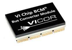
1. The overmolded package of the BCM bus converter adds additional thermal benefits and reduced impedance via case dissipation.
Similarly, the updated design and increased number of leads provide a simple, effective, low-impedance thermal path to the case or cold plate. So, it’s a thermal win in both convection and conduction (Fig. 2). There are even a few extra percentage points of cooling via convection through the sides, an extra benefit.
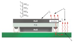
2. Modeling and analysis of the overmolded package shows the multiple, effective thermal paths it offers.
The mold compound also averages local thermal conditions to reduce dangerous hot spots and allows higher power to be drawn from a given unit. For example, while a Vicor VI Chip BCM Bus Converter module can deliver 330 W at a 100°C case temperature, that rating increases to 375 W at TCASE = 85°C, a 13.5% improvement in the same footprint.
As an added benefit, the overmolded package overcomes regulatory creepage (spacing) clearance challenges to enable higher input voltages, up to 400 V, in smaller converter packages, and higher inputs are a key factor to greater efficiency. Vicor offers modeling tools for overmolded packages so electrical and thermal supply performance can be analyzed in advance and with high confidence.
The tools are there, and the mandates are increasing. So do your thermal modeling early on to avoid the need to revisit and redesign, while also producing a better, more cost-effective product.
Stephen Oliver is vice president of the VI Chip product line for Vicor Corp. He has been in the electronics industry for 18 years, with experience as an applications engineer and in product development, manufacturing, and strategic product marketing in the ac-dc, telecom, defense, processor power, and automotive markets. Previously, he worked for International Rectifier, Philips Electronics, and Motorola. He holds a BSEE from Manchester University, U.K., and an MBA in global strategy and marketing from UCLA. He holds several power-electronics patents as well.
About the Author
Stephen Oliver
Vicor Corp., Power Design
Stephen Oliver, vice president of Vicor’s VI Chip Product Line, has been in the electronics industry for 18 years, with experience in applications engineering, product development, manufacturing, and strategic product marketing in the ac-dc, telecom, defense, processor power, and automotive markets. Previously with International Rectifier, Philips Electronics, and Motorola, he received a BSEE degree from Manchester University, the U.K., and an MBA in global strategy and marketing from UCLA. He holds several power electronics patents as well.
Comment About the Article
To join the conversation, and become an exclusive member of Electronic Design, create an account today!

Leaders relevant to this article: