Generate Realistic Models For LED Current Versus Voltage

This article is part of the Series: Ideas for Design: Ideas for Design Volume 2
Download this article in PDF format.
LEDs are nonlinear devices with I/V curves that resemble the curves of rectifier diodes. Designers of lighting drivers require a good approach to modeling the LED device performance in the first quadrant of the I/V plane.
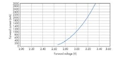
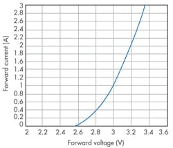
For engineering applications, there are three approaches to consider: the linear, bias-voltage plus resistor equivalent; a quadratic equation; and an exponential equation. Let’s use the three techniques with Cree’s XLamp XM-L LED as the LED to be modeled (Fig. 1).
The Linear Model
This model is the simplest, but the most inaccurate. It consists of a dc bias voltage plus a resistor (Fig. 2a). The equivalent mathematical form is given by:
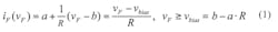
You select two data points (vF, iF) in coordinate form (i.e., 3.28 V, 2.6 A and 2.71 V, 0.2 A). Then, R is evaluated and yields 0.2375. The selection also implies a = 0.2 and b = 2.71. With all three parameters (a, b, R) properly assigned, the linear model yields Figure 2b. Evidently, the linear model offers the advantage of simplicity, but suffers in accuracy.
The Quadratic Model
The curve of Figure 1 has a concave portion that resembles one arm of a parabolic curve. It can be expressed with a quadratic equation of the form a2vF2 + a1vF + a0. The key is the determination of three coefficients: a2, a1, and a0.
To determine these coefficients, you can use the well-known Least Square Polynomial Curve-fitting algorithm of linear algebra. To do this, select more than a dozen data points from Figure 1 (15 in this case) and place them in two matrixes. One is a 3x15 rectangular matrix C:


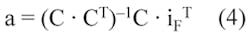
Using software tools such as Matlab from the Mathworks or MathCAD from the Mathsoft, you can easily compute Equation 4. For this example, we obtain:
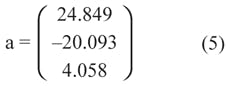
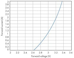
Note that that the first element of vector a is coefficient a0, etc., which leads to the quadratic model of Figure 3. This approach yields significant improvements in the model across the whole operating range of the LED.
The Exponential Model
Figure 3 appears to bend more near the low current, which is where the exponential model may offer further improvement. This model comes in the form of aeb·vF + c with three unknown parameters a, b, and c to be determined. Again, software tools such as MathCAD help you find those parameters numerically.
Under the specialized regression section, an exponential regression statement expfit ( vF, iF, vg) can find all three parameters, given a data set in vectors and initial guess value vg, also a column vector. For this example, a = 9.66 · 10–3, b = 1.818, and c = –1.157 are obtained. This results in the exponential model of Figure 4.
Overall, the best fit near the low-current region may lie between the quadratic and the exponential models. It is unrealistic to expect a single, perfect prediction from any given model, since almost all such analytical efforts are an attempt to represent the complexities of nature.
About the Author
Keng Wu
Keng C. Wu, a power electronics consultant, has published five books on power processing, was awarded “Author of the Year” twice (2003 and 2006 Lockheed Martin), and presented a 3-hour educational seminar IEEE APEC-2007 S17. He has held more than a dozen U.S. patents. He earned a BS from Chiaotung University, Taiwan, and an MS from Northwestern University, Evanston, Ill.
Comment About the Article
To join the conversation, and become an exclusive member of Electronic Design, create an account today!

Leaders relevant to this article: