Graphical, Numerical Techniques Size LED Array’s Drive

This file type includes high resolution graphics and schematics.
LED-based lighting is replacing incandescent and gas-discharge lamps in many situations. As practical lighting sources, and considering their directional nature, LED fixtures usually use multiple LEDs arranged in an array, with “m” LEDs in a serial string and “n” such strings in parallel (Fig. 1).
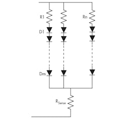
For the array configuration and the exponential I-V characteristics model of a single LED,1 it’s also possible to have a similar model representing the loading of such an array.
Related Articles
- Master The Fundamentals Of LED Illumination
- Generate Realistic Models For LED Current Versus Voltage
- Use Flyback Converters To Drive Your LEDs
Since the single LED is a diode with a nonlinear forward-voltage/current, driving it with a fixed voltage source is generally not recommended. Rather, a serial (current-limiting) resistor is needed to equalize the power source and the load,(Fig. 2).
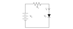
However, sizing this resistor requires a significant analytical manipulation. Using the single-LED exponential model, a Kirchoff’s voltage law (KVL) equation around the circuit loop gives:

which can be rearranged to:

where a, b, and c are model parameters for a selected LED, as defined in the reference.
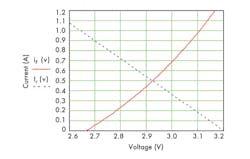
This is a challenge to solve symbolically, but it can be solved numerically with mathematical software tools. Alternatively, it can be solved graphically by separating the two key I-V relationship equations, v+ RxIF = Vs and IF = aebv + c.
For example, using a Lumileds Luxeon Rebel ES LED with a 3.2-V dc source and a desired drive current of 0.5 A, the horizontal current line intercepts the LED curve at 2.92 V (Fig. 3). Therefore, the series resistor will be Rx = (3.2 – 2.92)/0.5 = 0.56 Ω.
However, the graphical approach would not handle an LED array effectively, and the numerical method works better. To represent the array current iA, the exponential model for the (m × n) array is modified, since voltage drops across current-limiting resistor Rn and sense-resistor RSense are usually small compared with driving-source Vs:

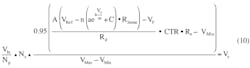
With the array model, the switch-mode buck-regulating current driver in a closed-loop configuration (Fig. 4) can be described by a set of equations starting at the feedback point, circling around the control loop, and ending at the driver output:
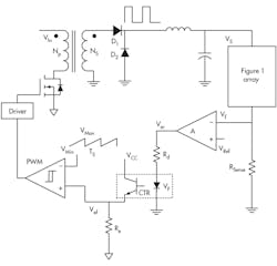
• Current sensing:
Vf = iA • RSense (4)
• Error amplifier:
Ver = A(VRef – Vf) (5)
• Effective error:


VRamp(D • Ts) = Vef (8)
• Power stage:

Reference
1.“Generate Realistic Models for LED Current Versus Voltage” Keng C. Wu; Electronic Design, Vol. 61, No. 1, p. 52, Jan. 10, 2013, http://electronicdesign.com/power/generate-realistic-models-led-current-versus-voltage
This file type includes high resolution graphics and schematics.
About the Author
Keng Wu
Keng C. Wu, a power electronics consultant, has published five books on power processing, was awarded “Author of the Year” twice (2003 and 2006 Lockheed Martin), and presented a 3-hour educational seminar IEEE APEC-2007 S17. He has held more than a dozen U.S. patents. He earned a BS from Chiaotung University, Taiwan, and an MS from Northwestern University, Evanston, Ill.
Comment About the Article
To join the conversation, and become an exclusive member of Electronic Design, create an account today!

Leaders relevant to this article: