Choose The Right Resistors For Medical Applications

This file type includes high resolution graphics and schematics.
Medical devices are leaving the confines of hospitals and serving the growing community-based and home-based healthcare markets. Growth in emerging economies is making populations more affluent, so people are healthier and living longer. However, growing pressure on costs parallels the ever-increasing demand for healthcare equipment.
In particular, analysts cite the need for faster, lower-power, higher-precision, and more intelligent electronic devices. Specific sub-segments with higher growth in electronics content include diagnostics, patient monitoring, and therapeutic equipment, predicted to expand at a rate of 9% per year between 2010 and 2017.1
Related Articles
- Build A Wrist Heart-Rate Monitor Using An Ultra-Low-Power MCU
- Biomedical Devices Improve And Extend Patient Lives
- Next-Generation Ultrasound Will Rely On Real-Time Compression
Portable and consumer medical devices are showing the highest growth rates. In 2016, the global health care equipment and supplies market will total $442.8 billion, an increase of 29.1% since 2011.2 The ever-improving computing power of digital systems is stimulating much of this development.
Since the human body is intrinsically analog, though, there will always be an important role for highly reliable passive components in systems including diagnostic, imaging, patient monitoring, instrumentation, and pharmaceutical delivery and dispensing applications. Approximately 20 passive components are needed for each active IC in a design.
Regulations and the unique characteristics of the healthcare environment impose a particular burden of care on designers choosing passive components such as resistors. Medical applications can be classified into three representative areas, each illustrating a different set of constraints for the electronics designer.
The first area, contact, includes all devices with an electrical connection to the body. For example, these devices deliver high-energy pulses for defibrillation, detect biologically generated signals for electrocardiograms (ECG) or electroencephalography (EEG), and measure body impedance for respiratory or plethysmographic monitoring.
Imaging encompasses X-ray, MRI, and ultrasound technologies, all with their own special demands on resistive components, in particular the ability to work with very high voltages and magnetic fields. Finally, medical instrumentation and analysis covers intravenous drip (IVD) and laboratory instruments where accuracy, repeatability, and stability are paramount.
Contact
To reduce the time-to-defibrillation delay and improve cardiac-arrest survival, health-service providers have increasingly turned to a strategy of wider access to defibrillation to augment emergency medical services. In some countries, automatic external defibrillators (AEDs) are provided to police, first aid volunteers, and even ordinary members of the public.
While AEDs pose the additional challenge of size- and cost-reduced components, all defibrillators need stable and repeatable measurement of the charging voltage, which determines the amount of electrical energy delivered to the patient. The defibrillator-charging circuit uses high-voltage resistors, with a high-value resistor, normally in the range of 5 MΩ to 50 MΩ, and a low-value resistor providing a potential divider for voltage feedback.
Critical features of such high-voltage resistors are linearity (expressed as voltage coefficient or VCR), temperature coefficient (TCR), and long-term stability under voltage stress. Thick-film resistors best suit this application. Their temperature characteristic is typically “U” shaped with limits expressed by the TCR, normally from ±25 to ±100 ppm/°C (Fig. 1). The TCR error can be reduced by choosing the highest-possible ohmic value, which lowers self-heating, and by designing layouts that avoid proximity to heat-generating components.
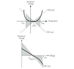
The voltage characteristic, by contrast, only ever has a negative gradient, with a limit expressed by the VCR, typically between –1 and –5 ppm/V. High-voltage resistors use special design techniques to minimize VCR, but this needs to be traded off against product size. As the gradient increases at high voltage, only operating the resistor at up to 75% of the full rated voltage can reduce VCR error. Designers need to choose resistors with both a low VCR and a high voltage rating. Furthermore, if the nominal VCR is known, compensation is relatively simple.
Environmental stability describes the limits of non-reversible resistance change under given loading and environmental conditions. The most demanding condition is high humidity, but some devices use a specially formulated high-density epoxy material to achieve typical resistance changes of less than 0.25% after 56 days at 95% relative humidity and 40ºC.
Pulse Protection
Exposure to defibrillation pulses is an issue for any directly connected monitors, such as ECG, respiratory, and plethysmographic monitors. In particular, damage to the sensitive input stages of such equipment must be prevented.
Also, it is even more important to avoid diverting the defibrillation energy from the patient, achieved by adding resistance to the monitor input circuit. This normally takes the form of a pulse-withstanding resistor built into the lead set. Secondary protection may be provided within the monitor itself.
The percentage of the total defibrillation energy received by a protection resistor depends on its ohmic value, so designers need to select the highest value consistent with that required by the monitor function. Designers also need to account for the actual test circuit chosen for the application. In addition, specific electromagnetic compatibility (EMC) standards, IEC601, are defined for medical equipment. IEC601 requires designers to factor in the number of leads in the lead set.
Energy ratings for the protection resistor should be in the region of 25 J at 1K falling to 2.5 J at 10K. Today’s carbon composition and high-surge metal glaze devices support this level of performance. PCB-mounted (printed-circuit board) resistors that provide secondary protection use pulse-withstanding thick-film products. Guaranteed pulse performance comes from resistors utilizing special materials and adjustment techniques. Double-sided resistors, providing two parallel resistance elements in a single chip, offer twice the energy capacity without compromising the size benefits.
ECG High Gain Amplification
Resistor innovations also are coming to the aid of contact medical applications in ECG monitors and analytical instruments that require sensitive first stages to amplify small signals. Here, high ohmic values are required in the feedback resistor—ratings outside the range normally available. To meet these needs, off-the-shelf flat chips provide resistance values up to 50 GΩ, whilst glass-sealed resistors extend capability right out to 100 TΩ (1014 Ω).
Imaging
Imaging applications include X-ray, ultrasound, and MRI systems. Each of these applications has its own requirements for resistive components. X-ray systems require stable and accurate high-voltage supplies to provide the accelerating voltage for X-ray generation, typically in the 50-kV to 100-kV range. Circuits are often assembled in an oil-filled chamber to reduce the clearance constraints on the layout, enabling a compact X-ray head design.
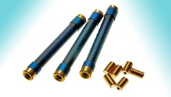
An effective design approach is to use an ultra-high-voltage thick-film resistor, selected from the specialized devices available that provide up to 100 kV in a single element in an oil-filled assembly (Fig. 2). Wire or screw termination options allow stacking into multiple resistor assemblies, while unsleeved versions eliminate the possibility of air pockets. Availability in matched sets ensures accurate ratio tolerance and facilitates designs with very low TCR through cancellation.
In contrast with X-ray imaging designs, ultrasound transducers require termination networks that can operate at high frequency and provide multiple channels of resistive termination. Standard or custom ball grid array (BGA) thin-film resistor networks can be produced to meet application requirements up to 15 MHz with 128 channels.
MRI scanners pose further challenges to designers, in particular the need for control circuits to operate inside extremely strong magnetic fields. Components must be free of ferrous alloys and nickel, the materials commonly used in the termination caps of most types of axial resistors or as anti-leaching barriers in chip resistors. Capless through-hole resistors and nickel-free chip resistors should be sought for such requirements.
Nonmagnetic solutions are also available for circuit protection in MRI scanners. For example, a recently developed non-magnetic fuse provides typical cutoff current of 995 mA for a rated dc current of 570 mA at 250 V dc. With residual magnetism of less than 1.0008, the fuse comes in surface-mount flip-chip packaging and can be tailored different fusing characteristics.
Analytical Equipment And Instrumentation
Precision resistors deliver the tight tolerances, low temperature sensitivity, and high stability demanded across a broad range of laboratory analysis equipment (Fig. 3). The input stage of an instrument with a resistive sensor, such as a thermistor in a precision temperature-monitoring circuit, consists of a bridge of resistors, which must be closely matched in value. Since it is the ratio between values that matters rather than absolute values themselves, the maximum difference between TCRs (that is, the tracking TCR) is more important than the absolute TCR.
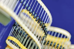
Most through-hole precision resistors including the RC series from TT electronics are available in matched sets with specified ratio tolerance and tracking TCR, providing the best available precision (Fig. 3). Alternatively, where space is a major consideration, surface-mount device (SMD) thin-film products with multiple elements can provide high precision in a compact single-component solution.
Options for the precision through-hole resistor approach range from semi-precision devices like the PR series from TT electronics through its RC series to ultra-precision devices capable of equalling the performance of costly metal foil technology using advanced metal film techniques. The precision SMD offering includes conventional thin-film chip resistors using nichrome elements. However, devices that exploit the self-passivating properties of tantalum-nitride film can meet ultra-high-stability requirements.
When evaluating the long-term stability of resistors, designers should consider several environmental tests. Some of these are early-life factors, such as exposure to solder heat. Others like TCR are reversible. Nevertheless, most are long-term factors. Best practice is to design based only on the figure that most closely reflects operating conditions.
Shelf life metrics apply where loading is negligible and the environment is benign, but the load figure should be applied where power dissipation is the main factor. For humid environments, designers should focus on measuring the long-term damp heat figure. In all these tests, most of the value change happens within the period of the test, as the value will tend to stabilize.
The figure of most value to designers is the maximum total error in resistance value at the end of product life, or before scheduled re-calibration if this is applicable. Known as the total excursion, it is calculated from the root of the sum of the squares (RSS) of applicable, statistically independent short-term and long-term factors. Applying this calculation to an ultra-precision MAR series resistor from TT electronics demonstrates an order-of-magnitude improvement in total excursion compared with standard precision resistors like the RC series.
Thick-Film Technology Extends The Applications
Thick-film technology developed for resistors has more recently come to the fore in new medical instrumentation applications, measuring impedance of test samples rather than current or voltage. One example uses impedance measurements to determine the rate at which cancerous cells are killed during chemotherapy.
A key requirement is material biocompatibility. In this case, using silver/silver-chloride (Ag/AgCl) contacts thick-film printed onto ceramics enables researchers to determine the effectiveness of different chemotherapy treatments on individual patient tumours. The results will help them develop bespoke treatments targeting specific cancers.
Similar technologies, also based on Ag/AgCl contacts atop dimensionally stable ceramic substrates, are being developed for measuring the impedance of tissue to provide faster and more reliable early detection of cancer and pre-cancerous cells. This promises better cervical cancer screening compared with existing methods.
Every year brings new applications like this, which are harnessing electronics to diagnose illness, monitor medical interventions, and keep both patients and healthcare workers safe. Innovations in resistors are providing designers with the solutions they need to meet all the challenges of performance, cost, and availability.
References
1. IHS iSupply Market Tracker, Industrial Electronics, Q3 2011
2. MarketLine Industry Profile Global Health Care Equipment & Supplies, June 2012

This file type includes high resolution graphics and schematics.
About the Author
Stephen Oxley
Business Development Engineer, Fixed and Variable Resistors, Sensors and Specialist Components division, TT Electronics
Stephen Oxley is Business Development Engineer for the Fixed and Variable Resistors, Sensors and Specialist Components division at TT Electronics . He has a master’s degree in electrical and electronic engineering from Bath University, the U.K.
Comment About the Article
To join the conversation, and become an exclusive member of Electronic Design, create an account today!

Leaders relevant to this article: