Determine Equivalent ESR, Ripple Voltage, And Currents For Unequal Capacitors In Parallel

This file type includes high resolution graphics and schematics.
Capacitors often are connected in parallel in power electronics to decrease high-frequency ripples, current stress, decrease power dissipation, and operating temperature, as well as to shape frequency response and boost reliability. Yet designers have three critical questions about this technique:
Related Articles
- How To Measure Ultra-Low Impedances
- Input Ripple-Current Balancing By Phase Shifting Multiple Outputs
- Free Simulation App Speeds Filter Design Process
• What are the equivalent values of capacitance Cse and equivalent series resistance (ESR) Rse?
• What is the high-frequency ripple voltage?
• What are the individual RMS currents?
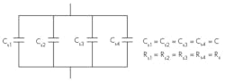
If all N capacitors in the parallel connection are identical (Fig. 1), with equal capacitance values Csk = C and equal ESR values Rsk = Rs, then for k = 1, 2, . . . N the answers are clear:
• Cse is directly proportional to the number of capacitors N: Cse = NC, and Rse is inversely proportional to N: Rse =Rs/N.
• Ripple voltage V (RMS value) is:

for a sinusoidal current excitation i(t) = I √2 sin (2πft) with frequency f, where Xse = 1/(2πfCse) is the reactance of the equivalent capacitor Cse and RMS value I, and individual RMS currents in the capacitors are identical: Ik = I/N.
When the capacitors in the parallel connection aren’t identical, with different capacitance Csk and ESR Rsk values, the solution to the problem isn’t trivial. The direct approach is to obtain an analytical expression for the input impedance of the parallel connection in the algebraic form Z = Re Z – j ImZ= Zse Z and use the formulas Rse = Re Z, Xse = Im Z, and Cse = 1/(2πf Xse).
A less complicated approach is based on the conversion of series Csk,Rsk connections to equivalent parallel Cpk, Rpk connections. To obtain relationships between Rpk and Rsk, and also between Cpk and Csk, set the admittance Ypk of the parallel Cpk, Rpk pair and admittance Ysk of the series Csk, Rsk pair connections equal to each other: Ypk = Ysk, Re (Ypk) = Re (Ysk), and Im (Ypk) = Im (Ysk). Then:


where:

is the reactance of the individual capacitor.
After individual parallel capacitances Cpk and resistances Rpk are calculated according to Equations 2 and 3, equivalent parallel capacitance Cpe can be easily found as the sum of Cpk:

The real part of equivalent admittance can be found as the sum of admittances 1/Rpk. Rpe can be obtained as a reverse value of that sum:

The system’s equivalent series capacitance Cse and ESR Rse can be found by conversion of the parallel Cpe, Rpe connection to the equivalent series connection Cse, Rse. To obtain relationships between Cse and Cpe and also between Rse and Rpe, set impedance Zpe of the parallel Cpe, Rpe and impedance Zse of the series Cse, Rse connections equal to each other: Zpe = Zse, Re Zpe =Re Zse, Im Zpe = Im Zse. Then:


where:

is the reactance of the equivalent parallel capacitor Cpe(Equation 5).
Based on this analysis, the calculation procedure for equivalent series capacitance Cse, ESR Rse, voltage ripples V, and RMS currents Ik in the capacitors is:
• Calculate reactances of individual capacitances according to Equation 4.
• Determine equivalent parallel parameters Cpk, Rpk of the capacitors based on Equations 2 and 3.
• Calculate equivalent parallel capacitance Cpe of the structure, its reactance Xpe, and equivalent parallel resistance Rpe according to Equations 5, 9, and 6.
• Calculate equivalent series capacitance Cse and ESR Rse of the structure according to Equations 7 and 8.
• Obtain RMS ripple voltage V using Equation 1.
• Calculate RMS currents Ik in the capacitors based on:

Note that ESR values Rsk are strong functions of frequency. A designer should use ESR data specified by capacitor manufacturers at a given frequency of operation, such as the data for ceramic and polymer aluminum electrolytic capacitors from Murata Manufacturing Co. Ltd. (MMC) (http://ds.murata.co.jp/software/simsurfing/en-us/index.html).
To illustrate the calculation procedure, let’s determine equivalent parameters, voltage ripple, and current distribution for a parallel connection of three ceramic capacitors (GRM21BR60J226ME39L) and one polymer capacitor (ESASD40J107M015K00) from MMC (Fig. 2).
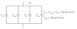
Using the data f = 200 kHz, Cs1 = Cs2 = Cs3 = 22 μF, Rs1 = Rs2 = Rs3 = 4 mΩ, Cs4 = 100 μF, Rs4 =8 mΩ, I = 2 A, then:
• For reactance of each individual capacitance according to Equation 4, we have Xsi = Xs2 = Xs3 = 3.6 mΩ, Xs4 = 0.8 mΩ.
• Equivalent parallel parameters Cpk, Rpk of the capacitors based on Equations 2 and 3 are Cp1 =Cp2 = Cp3 = 21.7 μF, Rp1 =Rp2 = Rp3 = 331 mΩ, Cp4 = 49.7 μF, Rp4 = 16 mΩ.
• For equivalent parallel capacitance Cpe, its reactance Xpe and equivalent parallel resistance Rpe of the structure according to Equations 5, 9, and 6, we calculate Cpe = 115 μF, Xpe = 6.9 mΩ, Rpe = 13.9 mΩ.
• According to Equations 7 and 8, the equivalent series capacitance Cse and ESR Rse are Cse = 143.4 μF, Rse = 2.76 mΩ.
• For RMS ripple voltage V based on Equation 1, we obtain V = 12.4 mV.
• RMS currents according to Equation 10 in ceramic and polymer capacitors are respectively: I1 = I2 = I3 = 341 mA, I4 = 1.1 A.
This shows the technique can easily determine the parameter values in each of the capacitors.
Alexander Asinovski is principal engineer at Murata Power Solutions Inc., Mansfield, Mass. He holds BSEE and MSEE degrees from State Technical University, St. Petersburg, Russia, and a PhD from the University of Telecommunications, St. Petersburg. He can be reached at [email protected].
This file type includes high resolution graphics and schematics.
About the Author
Alexander Asinovski
Principal Engineer
Alexander Asinovski is principal engineer at Murata Power Solutions Inc., Mansfield, Mass. He holds BSEE and MSEE degrees from State Technical University, St. Petersburg, Russia, and a PhD from the University of Telecommunications, St. Petersburg. He can be reached at [email protected].
Comment About the Article
To join the conversation, and become an exclusive member of Electronic Design, create an account today!

Leaders relevant to this article: