Electronic Design
  • Resources
  • Directory
  • Webinars
  • CAD Models
  • Video
  • Blogs
  • More Publications
  • Advertise
    • Search
  • Top Stories
  • Tech Topics
  • Analog
  • Power
  • Embedded
  • Test
  • AI / ML
  • Automotive
  • Data Sheets
  • Topics
    - TechXchange Topics --- Markets --AutomotiveAutomation-- Technologies --AnalogPowerTest & MeasurementEmbedded
    Resources
    Electronic Design ResourcesTop Stories of the WeekNew ProductsKit Close-UpElectronic Design LibrarySearch Data SheetsCompany DirectoryBlogsContribute
    Members
    ContentBenefitsSubscribeDigital editions
    Advertise
    https://www.facebook.com/ElectronicDesign
    https://www.linkedin.com/groups/4210549/
    https://twitter.com/ElectronicDesgn
    https://www.youtube.com/channel/UCXKEiQ9dob20rIqTA7ONfJg
    Electronicdesign 7028 0314prodtrendspromo
    1. Technologies
    2. Power

    SEPIC-Fed Buck Converter’s Lowered Losses Elevate Efficiency

    Feb. 6, 2014
    Two critical issues, efficiency and transient response, continue to tag-team the power-electronics arena. CUI takes them on with its patented SEPIC-fed buck (SFB) converter.
    ED News Staff

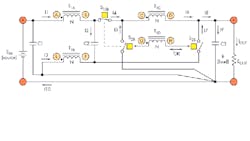
    Two critical issues, efficiency and transient response, continue to tag-team the power-electronics arena. CUI takes them on with its patented SEPIC-fed buck (SFB) converter (Fig. 1). The SFB topology fundamentally improves power-conversion efficiency and transient response while retaining the simplicity and low cost of a synchronous buck converter.

    Electronicdesign Com Sites Electronicdesign com Files Uploads 2014 02 0314 Prod Trends F1 Large 0
    1. In this non-isolated implementation of the SEPIC-fed buck converter, the commutation switches are shown as ideal switches. They can be implemented as synchronous rectifiers. The SEPIC and buck are combined into a single couple inductor to facilitate energy storage and transfer.

    Related Articles

    • Optimize Your POL Buck-Converter Integration
    • Fundamentals Of Buck Converter Efficiency
    • Improved Power ICs Give Supply Designers More Bang For The Buck

    The topology tackles both conductivity losses and switching losses. To overcome the I2OUTR losses in the buck converter, multiple energy delivery paths are made available to split the load current. It integrates a buck converter into a single-ended primary inductor converter (SEPIC) so it receives energy from the SEPIC inductors. The outputs of both deliver energy to the load in parallel.

    Insidepenton Com Electronic Design Adobe Pdf Logo Tiny
    Download this article in .PDF format
    This file type includes high resolution graphics and schematics when applicable.

    When the controlling switch shared by both converters is ON, the buck portion delivers energy to the load while the SEPIC portion stores energy in the magnetic element and feeds the buck portion. When the controlling switch is OFF, both the buck and SEPIC portions deliver stored energy to the load.

    An extremely fast, controlled turn-off commutation of the control switch, made possible by a gate-charge extraction (GCE) mechanism inherent in the topology, addresses the significant turn-off loss issue in the buck. Lower voltage and current stresses on the power switches also dramatically reduce their turn-on losses. On the transient response, reduced current level on the integrating inductors and increased reset voltage bring fundamentally faster response from the power stage.

    The converter has a voltage-transfer ratio of EOUT/EIN = (2 – D), and it complementarily combines the characteristics of both the buck and SEPIC converters. This reduces voltage and current levels in the magnetic and switching devices, which in turn reduces conduction and switching losses. In addition, a new volt-second structure on the magnetic element boosts the power stage’s transient response.

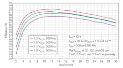
    Testing results, using a prototype SFB converter at 300 and 500 kHz, revealed that despite the relatively high on resistance of the switches that were used and the additional power loss from the current transformer, the device still achieved efficiencies of 86.9% at 1 V (at 300 kHz) and 88.0% at 1.2 V (at 500 kHz) (Fig. 2).

    Electronicdesign Com Sites Electronicdesign com Files Uploads 2014 02 0314 Prod Trends F2
    2. Testing of a prototype SFB converter, at 300 and 500 kHz, produced efficiencies of 86.9% at 1 V and 88.0% at 1.2 V, respectively.

    If updated with newer devices that have an on resistance of 1.8 Ω, nearly 835 and 880 mW of conduction losses are saved at 1.0 and 1.2 V, respectively. Furthermore, if the control scheme is changed to voltage-mode control, combined power savings at the switches and transformer would increase efficiency to about 90.0% and 90.9% at 1.0 and 1.2 V, respectively.

    Results also show that the efficiency difference between 300 and 500 kHz is minimal, indicating that frequency-dependent switching losses are relatively small in the SFB converter, smaller than in the buck converter.
    Continue Reading

    Maximizing Power from Solar Panels

    A Guide to Battery Fast Charging (Part 2)

    Sponsored Recommendations

    CoolSiC™ Products

    Nov. 17, 2023

    Modular systems with high performance and high application efficiency

    Nov. 17, 2023

    The Infineon Podcast4Engineers

    Nov. 17, 2023

    Depth Sensors Visualize Volumes

    Nov. 1, 2023

    Comments

    To join the conversation, and become an exclusive member of Electronic Design, create an account today!

    I already have an account

    New

    Arm Unveils Its Most Compact AI-Capable Cortex-M CPU

    Welcome to GoPro Warfare

    Lead-Free Quantum Dots Bring SWIR Closer to Consumers

    Most Read

    Arm Unveils Its Most Compact AI-Capable Cortex-M CPU

    New Tech Helps Keep High-Speed Serial Connections Cool

    From Design to Delivery: Creating Embedded System Solutions


    Sponsored

    How GaN enables high efficiency in totem-pole PFC-based power designs

    How to Use Integrated GaN Switches for High Efficiency, Cost-Effective Offline Power Supplies

    Signal Chain Power (SCP) Hardware Evaluation Platform

    Electronic Design
    https://www.facebook.com/ElectronicDesign
    https://www.linkedin.com/groups/4210549/
    https://twitter.com/ElectronicDesgn
    https://www.youtube.com/channel/UCXKEiQ9dob20rIqTA7ONfJg
    • About Us
    • Contact Us
    • Advertise
    • Do Not Sell or Share
    • Privacy & Cookie Policy
    • Terms of Service
    © 2023 Endeavor Business Media, LLC. All rights reserved.
    Endeavor Business Media Logo