Simple Soft-Start Circuitry Provides Long Startup Times

Download this article in .PDF format
Many dc-dc converters require relatively large amounts of input current at startup (when input power is first applied). A soft-start function minimizes this large input current by gradually increasing the switch-current limit at startup, slowing the rate of rise of the output voltage and reducing the peak current required when starting up.
Some switching-regulator ICs include a short soft-start period (100 µs to 3 ms), but in some instances the start-up currents are still large enough to cause problems. The major problem occurs when the input power source to the switching regulator is current-limited or has poor load regulation, both of which will cause the input voltage to drop when large startup currents are required.
Because of the negative resistance characteristic associated with the inputs of many switchers, insufficient soft-start time will result in high input currents, causing the input voltage source to be pulled down. With a lower input voltage, the switching regulator requires even more input current to correctly start up. This, in turn, will pull the input voltage lower still, resulting in a latch condition. When in a latch condition, the input current is relatively high, the input voltage is pulled low, and the switching regulator’s output never reaches its regulated value. Because of the charging of the output capacitor, this high startup current can exist even without a load on the switcher’s output.
Besides minimizing the high startup current associated with switching regulators, a soft-start function also can be used for power supply sequencing. In some situations where multiple regulated voltages are present, it may be necessary for one or more voltages to come up after the main power has come up and stabilized.
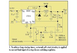
The circuit in the dashed box of Figure 1 can be applied to many different types of switching regulators, including buck, boost, flyback, and SEPIC. It provides a soft-start function by slowly increasing the switch current limit, thus controlling the output voltage slew rate. At startup, the output voltage increases linearly, with ramp times ranging from milliseconds to seconds, depending on the capacitor value. The compensation pin (VC pin) in many current-mode switching-regulator ICs is the output of the error amplifier, which directly controls the maximum current through the switch. By limiting the voltage at the VC pin, the current can be controlled.
Referring to Figure 1, the circuit operates as follows. At startup, when the input voltage is first applied or when the shutdown input goes high, the regulator output voltage begins to rise. The soft-start capacitor (CSS) begins charging through the emitter-base of Q1, causing the collector to begin pulling down on the compensation (VC) pin (pin 6), thus lowering the switch current limit. Because of this feedback loop, the charge current for the soft-start capacitor is a constant 10 µA, which is determined by R1 (68k) and the VBE (≈680 mV) of Q1.
When the regulator’s output voltage has stabilized and the soft-start capacitor is charged, the transistor turns off and the switching-regulator circuit operates normally. R2 limits the discharge current of CSS at powerdown to protect the emitter-base of Q1. The following formula can be used to determine the total startup time for various output voltages and soft-start capacitor values:
t = CSS * VOUT /10 µA
The two photos in Figure 2 show the input current and the output voltage of a buck switching-regulator circuit at startup.

The left photo is the regulator’s performance without the external soft-start circuitry, whereas the one on the right shows the effect of the external soft-start circuit of Figure 1. As the right photo illustrates, the 3.8-A input surge current is completely eliminated, while the output voltage increases linearly in approximately 5.5 ms. Other capacitor values can be used if faster or slower rise times are desired. Although a stepdown (buck) regulator configuration was used for the photos, other topologies will provide similar results.
About the Author
Comment About the Article
To join the conversation, and become an exclusive member of Electronic Design, create an account today!

Leaders relevant to this article: