Isolated Circuit Digitally Indicates 120-/220-V Line Voltage
This file type includes high-resolution graphics and schematics when applicable.
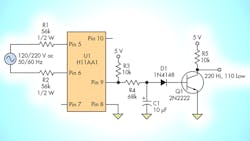
For applications such as motor control or power supplies, it’s often necessary to know whether the ac line is at 120 V or 220 V to adjust the operation. The circuit illustrated in the figure monitors the ac line and provides a basic output indicating whether it is at 120 V or 220 V, with the output at the transistor collector going low for 120-V and high for 220-V inputs.
The principle behind the circuit is to make the output of the optocoupler LEDs high enough at 220 V so that it will drive the internal phototransistor to turn transistor Q1 (a standard 2N2222) off to produce a high output, but low enough at 120 V for the phototransistor to turn Q1 on and yield a low output. Optocoupler U1 was chosen because it’s rated and certified for line-voltage applications.
The ac-voltage input goes through resistors R1 and R2 and drives the back-to-back (antiparallel) LEDs inside U1. The LED current, about 1 mA at 120 V and 2 mA at 220 V, is set low to minimize the degradation in current transfer ratio (CTR) over time, which is common with optocouplers (see references). Voltage spikes, which occur at the output of U1 due to the zero crossings where the LEDs aren’t conducting, are narrowest at 220 V as the phototransistor is driven to saturation.
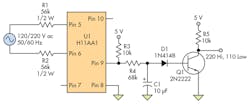
After RC filtering with a 0.7-second time constant, the average voltage isn’t sufficient to turn on Q1; thus, the output is high. Since the current at 120 V is insufficient to fully drive the phototransistor, its output is pulled up by R3 (after filtering by C1/R4) and drives Q1 into saturation. In effect, Q1 is functioning as a low-gain comparator that’s slowly switching between the high and low states at the "don’t care" line voltages of 150 to 170 V, 50/60 Hz.
When the line is at 120 V, there’s short period of about one second at power on when the output will go high and then low, while the capacitor is being charged. This temporary state may need to be ignored, depending on your monitoring circuit. If the 120-V input will always be at 60 Hz, or the 220 V will always be at 50 Hz, and if the monitoring circuit has some time-measuring capability, C1 can be removed. This results in a square wave that can be used to measure the half-period of the ac input (8.33 ms for 120 V and 10 ms for 220 V). Finally, if the output is coupled into a low-impedance load, it's a good idea to buffer the output with an emitter-follower transistor stage to reduce the loading.
Edward K. Miguel is now an independent contractor in DeKalb, Illinois, who has worked for 40 years in design and management, specializing in frequency control. He received his BS and MS in EET from Northern Illinois University, with a specialty in quartz frequency control. He can be reached at [email protected].
References:
Calculate Reliable LED Lifetime Performance in Optocouplers,” Avago Technologies/Broadcom
"How to simulate Current Transfer Ratios (CTR) and long-term CTR degradation in transistor optocouplers,” California Eastern Laboratories
"Study and Modelling of Optocouplers Ageing,” Journal of Automation & Systems Engineering
About the Author
Comment About the Article
To join the conversation, and become an exclusive member of Electronic Design, create an account today!

Leaders relevant to this article: