Testing for IoT Power Concerns

Download this article in PDF format.
Like all embedded systems, those considered part of the Internet of Things (IoT) require power, and that power needs precise management for the system to function as designed. A typical IoT-related system will comprise a number of elements that generate and/or process analog, digital, and serial-data signals.
Consider a generic example of an IoT system (Fig. 1), consisting of a 32-bit CPU, power-supply block, digital I/O, DDR, an FPGA, and more. Such systems might also include sensor signals, making it what some might call a “deeply embedded” system, as well as some form of wireless connectivity such as a Bluetooth transceiver. Powering it all is a (typically) 12-V supply that feeds a power-management IC (PMIC).
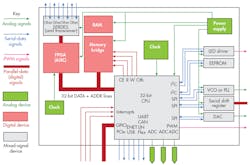
1. Shown is a representative typical IoT device requiring digital power management to control various dc-dc converter voltages to ensure quick and accurate power delivery over one or more dc power rails.
Such a system would require digital power management controlling various dc-dc converter voltages to ensure quick and accurate power delivery over one or more dc power rails. To ensure power integrity, we’d want to analyze whether the converters provide the expected voltage and current to the various power rails. It’s also critical that voltage/power-rail sequence testing confirm that ramp times and the order of rail power-ups serve the system well.
Digital Power-Management Overview
An IoT system’s power comes from a 12-V supply initially, which feeds one or more power rails at different voltages (3.3, 1.8, 1.5, and 1.1 V). These rails in turn supply power to the CPU and other on-board devices. For efficiency’s sake, each dc-dc supply typically comprises several dc-dc converters in parallel. These four converters are known as “phases” or “channels.” For example, the 1.1-V rail might actually be supplied by four 1.1-V converters in parallel, each supplying 25% of the total output current to the rail.
The phases of a given dc-dc converter, such as the 1.1-V example above, are switched on and off by a PMIC in concert with the load’s changing power requirements. The PMIC time-interleaves the PWM outputs into a single output. In turn, the PMIC takes its orders from the CPU to ensure proper current supply to all devices on the rail.
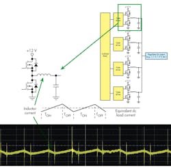
2. Each dc power rail’s supply typically comprises several dc-dc converters in parallel that are controlled by a PMIC.
The half-bridge output of each phase is commonly called the “inductor current,” because it flows through the output inductor, which serves to filter the output (Fig. 2). The output increases, or ramps up, when PWM signals are on, and decreases, or ramps down, when they’re off. Additional load capacitance further filters the output.
Ideally, each PMIC phase is balanced when under a steady-state load condition. The phases should be at the same amplitude as determined by voltage PWM. Each phase’s relationship to the other three phases is (1/fs)/N, where fs is the power semiconductor device’s switching frequency and N is the number of phases.
If amplitude errors occur between the different phases, there will be output ripple. If the amplitude errors are accompanied by phase errors, the result will be more complex distortion patterns.
Acquiring DC Power/Voltage Rails
There are three ways to acquire dc power/voltage rails. One method is by means of a 50-Ω coaxial cable terminated at the oscilloscope’s input with a 1-MΩ dc coupling. This method delivers reasonable noise performance, but requires either high offset capability of the oscilloscope or the use of a dc block. Reflections may occur due to impedance mismatches. There also are bandwidth limitations with a frequency response of <1 GHz.
A second method is to use a conventional 10X passive probe. However, this method suffers from poor noise performance, bandwidth limitations, and maximum gain-setting limitations.
The third, and preferred, method, is to use a specialized active voltage-rail probe. Such probes, like Teledyne LeCroy’s RP4030, offer lower loading on the dc rail and 1.2X attenuation to keep noise at a minimum.
Transient Rail Response Analysis
An important measurement for IoT digital power management is the transient response of a dc rail and its associated PMIC. What happens when loading is suddenly added or subtracted? This is a dynamic test that’s best served by a long capture time. A longer capture facilitates correlation of the load change with other signals, such as serial data commands, clocks/strobes, and enable lines.
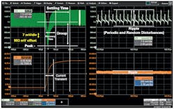
3. Test of a dc power rail’s transient response means measurement of a number of parameters to ensure that the rail is operating within spec.
In testing a single dc rail’s transient response, we want to ensure that tolerances are met for characteristics such as mean voltage value, ripple, ringing, peak min/max values, settling time, and droop (Fig. 3). When testing multiple dc rails and PMICs, the tests are the same. However, the objective in the case of multiple rails and PMICs is to determine the impacts of load changes on all rails at the same time.
In cases where a single PMIC is handling multiple phases, it’s extremely important to test for PMIC load/current sharing/tracking. The idea is to measure the voltage/current on each individual phase output. However, doing so can be difficult because the outputs of PMICs are often inaccessible. A solution to this problem is posed in a paper presented at DesignCon 2017 titled, “A Generic Test Tool for Power Distribution Networks.”
Voltage/Power-Rail Sequence Testing
For any system to start up correctly, the dc rails must turn on in a specific order with specific wait times between each one’s power-up. In this respect, IoT devices are no different from a laptop. For example, a device’s 3.3-V bus might go high first, followed 200 to 500 ms later by the 1.8-V bus, followed another 200 to 500 ms later by the 1.5-V bus, and so on.
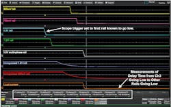
4. Power sequence testing ensures that the various dc power rails within the IoT turn on (and off) in the proper order and at specified intervals. This screen capture shows a power-down sequence test.
The sequencing tests call for acquisition of as many dc rail signals as possible (Teledyne LeCroy’s eight-channel HDO8000 oscilloscopes are well-suited for such applications). In addition, other signals such as clocks, PMIC enable signals, strobes, and serial-data commands to the PMIC should also be acquired for purposes of examining correlations. Timing between signals is measured using cursors or with measurement parameters. Sequence testing calls for long acquisition times with a high sampling rate. It’s useful to have as much acquisition memory as possible (up to 250 Mpoints of memory).
Sequence testing is useful on power-down of the device as well as at power-up. Figure 4 shows a screen capture of a voltage/power-rail power-down sequence. The oscilloscope was set to trigger on the first rail known to go low, which in this case was the 1.5-V rail (Channel 3). Power-down sequence timing was determined by measuring the delay times from Channel 3 going low to other voltage rails going low.
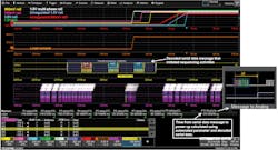
5. Testing for proper power sequencing can be based on serial-data trigger/decode of the control messaging that initiates the sequence.
A properly equipped oscilloscope can also determine power-rail sequencing using serial-data trigger/decode capabilities (Fig. 5). One might trigger on a serial-data message that initiates the power-up sequence, decode it, and use it as the basis for automated timing measurements that calculate the timing for power-up sequencing.

About the Author

David Maliniak
MWRF Executive Editor
Comment About the Article
To join the conversation, and become an exclusive member of Electronic Design, create an account today!

Leaders relevant to this article: