MEMS-Sprung Mirror Enables In-Path Laser-Power Measurement
Measuring laser power is a challenge. You can concentrate the energy on a sensor and measure the resultant temperature rise, or divert a known fraction of the beam power and gauge against that amount. For the first option, the laser must be switched (diverted) from its normal path; therefore, it can’t be used in production mode. In both options, with the extremely high-power lasers used for applications such as cutting and welding metals, it’s all too easy to literally burn out the sensor if things aren’t “just right.”
Researchers at the National Institute of Standards and Technology (NIST) are obviously aware of challenges, and recently devised a system for measuring the power of lasers in the higher-kilowatt range (up to 500 kW). They used a mirror that intercepts and reflects 99.9% of the beam, thus allowing the beam to continue its primary function. That setup, about the size of a shoebox, has a precision balance to measure the force (radiation pressure) of impinging photons, which is about 330 mg for a 100-kW beam, see “Gauging Multi-Kilowatt Laser Power with the Pressure of Light.”
But that approach isn’t compatible with much-lower beam intensities on the order of several hundred watts, so the NIST researchers have gone to an entirely different sensing scheme. Instead of measuring the tiny laser force impinging on a mirror, they devised a conceptually simple “smart mirror” approach (Fig. 1). The new design is both compact and suitable for embedding in the optical path, so that it doesn’t interfere with the use of the laser—a major advantage in real-world situations. Their detailed IEEE Sensor paper, “Micromachined force scale for optical power measurement by radiation pressure sensing,” goes beyond providing physics and functional details, as it also discusses its shortcomings and the project’s longer-term goals (there’s a much-less technical, 90-second video here).
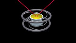
1. In this smart-mirror prototype, the laser light bounces off the highly reflective surface of a Bragg-reflector silicon plate, visible in the middle of a thick black ring of plastic. (Source: Jennifer Lauren Lee/NIST)
The heart of the sensor is a MEMS-based capacitor assembly consisting of two identical plates, each about 20 mm across and separated by 42.5 μm (Fig. 2). The top plate sensing element is a silicon disk attached to a silicon ring through three narrow spiral legs (with a width of 265 μm, thickness of 380 μm, and length of 45 mm). It’s fabricated as a distributed Bragg reflector, a highly reflective mirror made of alternating layers of silicon and silicon dioxide. Unlike a conventional mirror, the spacing and arrangement of the layers allows it to be tuned for maximum reflectivity at a desired wavelength.
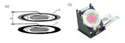
2. Shown is a schematic representation of the sensor mechanical system (a) and a photograph of a fabricated sensor (b). In (a), the mirror-coated silicon disk (b) is attached to a supporting silicon ring (a) through thin spring legs (c) in the shape of an Archimedean spiral, and the disk deflection is sensed by a capacitance change in a parallel plate capacitor through a pair of conductive electrodes (d) on the back side of each disk. Electrical connections (e) to the sensing electronics are provided through metallized extended pads (f). (Source: NIST)
The coupled disks serve to reject common-mode mechanical noises such as vibration or tilts as both plates move identically (or very nearly so). Researcher John Lehman commented, “If the device gets physically moved or vibrated, both plates move together, so the net force is strictly the radiation pressure, rather than any ambient influences.”
Light impinging on that top plate produces a force that moves it closer to the bottom plate and changes the assembly’s capacitance; the spacing is directly related to the photon pressure. To measure the change in capacitance, the prototype uses an open-loop signal-processing weigh scale (Fig. 3). The sensor is arranged in a bridge formation that’s driven by a sine wave, and the bridge output is amplified and synchronously demodulated to suppress preamplifier and low-frequency noise.
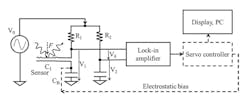
3. This simplified block diagram of a capacitive force scale shows the optical force applied to variable capacitor C1. The force-dependent AC-bridge signal is measured by a lock-in amplifier, and a servo controller could be added for closed-loop control of the electrode spacing of C1. The large-value capacitor CB decouples the dc electrostatic-bias path from the ac-bridge electronic readout. (Source: NIST)
The open-loop arrangement is highly nonlinear. It requires careful characterization to determine the initial zero-point rest state to properly gauge the sensor’s responsivity to laser power.
To enhance performance, they plan to move to a closed-loop null-indicator approach, which is common in high-performance measurements, where a servo controller uses electrostatic force to deflect the sensing plate to a pre-set bias point. Then, as the spacing between the two plates decreases, the servo controller adjusts this biasing force to return the MEMS spring and plate to its original null position.
Although the closed-loop architecture requires extra circuitry, it results in far-better performance and cancels some error sources, such as knowing the sensor spring constant. (This closed-loop “return to zero point” technique has been used for decades, for applications such as nulling the gimbaled platform supporting an inertial measurement system using mechanical gyroscopes, see “References” below.)
Their proof-of-concept device operated in open loop (without the nulling electrostatic force) with a 250-W laser. It had a response time under 20 ms, with noise floor of 2.5 W/√Hz, dominated by electronics.
The authors make clear that this work is still in the early stages. In addition to circuit noise, there are many second- and third-order error factors to consider and calibrate to enhance sensitivity and stability (including the permittivity of air). With further work, they hope to make a usable sensing system for powers between about 1 W and 1 kW. This power-measurement subsystem could even be packaged within the laser system and optical path for continuous real-time readings, which would yield significant operating benefits.
References
Donald MacKenzie, “Inventing Accuracy: A Historical Sociology of Nuclear Missile Guidance”
Anthony Lawrence, “Modern Inertial Technology: Navigation, Guidance, and Control”

About the Author

Bill Schweber
Contributing Editor
Bill Schweber is an electronics engineer who has written three textbooks on electronic communications systems, as well as hundreds of technical articles, opinion columns, and product features. In past roles, he worked as a technical website manager for multiple topic-specific sites for EE Times, as well as both the Executive Editor and Analog Editor at EDN.
At Analog Devices Inc., Bill was in marketing communications (public relations). As a result, he has been on both sides of the technical PR function, presenting company products, stories, and messages to the media and also as the recipient of these.
Prior to the MarCom role at Analog, Bill was associate editor of their respected technical journal and worked in their product marketing and applications engineering groups. Before those roles, he was at Instron Corp., doing hands-on analog- and power-circuit design and systems integration for materials-testing machine controls.
Bill has an MSEE (Univ. of Mass) and BSEE (Columbia Univ.), is a Registered Professional Engineer, and holds an Advanced Class amateur radio license. He has also planned, written, and presented online courses on a variety of engineering topics, including MOSFET basics, ADC selection, and driving LEDs.
Comment About the Article
To join the conversation, and become an exclusive member of Electronic Design, create an account today!

Leaders relevant to this article: