Special Drivers Boost BLDC Motor Performance (.PDF Download)
Brushless dc (BLDC) motors offer multiple benefits over other types of dc motors. They’re efficient, reliable, run at high speeds, are compact for their power level, and produce little or no EMI. However, drive circuit complexity and cost have limited their adoption.
The good news is that recent developments in semiconductor drive circuits are making BLDC motors more desirable. In fact, these new drive circuits may influence you to make BLDC motors your first choice for new motor-based consumer appliances and industrial products.
BLDC 101
Brushless dc motors, unlike more common dc motors, have a strong permanent magnet rotor and fixed stator windings. The windings are usually connected in a three-phase configuration requiring three different drive signals to three sets of windings. The driving signals are applied by a controller to create a rotating magnetic field that interacts with the poles on the rotor to produce a smooth continuous rotation.
The controller gets its inputs from position sensors carefully located around the perimeter of the stator. These are often Hall-effect sensors that tell the controller when to turn the drive voltages off and on, creating the rotation. The stator windings are usually driven by MOSFET half-bridge circuits. IGBTs are used to drive larger motors with higher voltage-current needs.
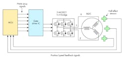
Figure 1 shows a simplified arrangement. Note that a microcontroller produces the initial drive pulses that are conditioned by the gate drivers to operate the MOSFET switches connected to the windings X, Y, and Z.

1. Shown is the general configuration of a BLDC motor and its drive system.
