Dual Stepper-Motor Driver IC Eliminates Current-Sense Resistor
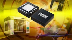
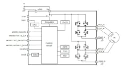
It’s often desirable or even necessary in motor-drive applications to sense the load current for feedback and fault monitoring. While this usually requires adding a discrete low-ohm resistor on the high side of the driver, the Toshiba TC78H670FTG two-phase bipolar stepper-motor driver eliminates the need for any external current-sense resistor by incorporating on-chip current detection (see figure). This configuration cuts cost and shrinks overall footprint.
The IC, which has integral dual H-bridges, is suitable for controlling motors in applications such as 3D printers, cameras, security cameras, portable printers, handheld scanners, pico-projectors, and battery-powered medical devices.
It can drive a micro-stepping motor of up to 128 steps with a voltage ranging from 2.5 to 16 V at currents of up to 2 A. On-resistance (R(DSON)), a critical figure of merit, is just 0.48 Ω due to use of Toshiba’s latest-generation CDMOS process. It delivers a PWM-controlled, constant-current drive from a supply ranging from 2.5 to 16.0 V. Standby current is just 0.1 µA for extended battery life, and it supports a 1.8- to 5.0-V interface for connection to a wide variety of hosts and microcontrollers.
Fault and error detection are also important attributes in a motor driver. The TC78H670FTG includes multiple error-detection functions including thermal shutdown, overcurrent, motor load open, and undervoltage lockout, with an error-detection flag output function. The oscillation frequency and chopping frequency, which are coupled, can be adjusted by an external resistor from 636 to 3290 kHz and 41 to 206 kHz, respectively. (As always, there are tradeoffs: as the chopping frequency increases, the drive-current ripple decreases, but the gate losses and dissipation also increase; a chopping frequency in the range of 50 to 100 kHz is recommended.)
The motor-driver IC is housed in 16-lead, 3- × 3-mm QFN package with thermal pad. Full details are provided in the extensive TC78H670FTG datasheet.
About the Author

Bill Schweber
Contributing Editor
Bill Schweber is an electronics engineer who has written three textbooks on electronic communications systems, as well as hundreds of technical articles, opinion columns, and product features. In past roles, he worked as a technical website manager for multiple topic-specific sites for EE Times, as well as both the Executive Editor and Analog Editor at EDN.
At Analog Devices Inc., Bill was in marketing communications (public relations). As a result, he has been on both sides of the technical PR function, presenting company products, stories, and messages to the media and also as the recipient of these.
Prior to the MarCom role at Analog, Bill was associate editor of their respected technical journal and worked in their product marketing and applications engineering groups. Before those roles, he was at Instron Corp., doing hands-on analog- and power-circuit design and systems integration for materials-testing machine controls.
Bill has an MSEE (Univ. of Mass) and BSEE (Columbia Univ.), is a Registered Professional Engineer, and holds an Advanced Class amateur radio license. He has also planned, written, and presented online courses on a variety of engineering topics, including MOSFET basics, ADC selection, and driving LEDs.

