5W Wireless Power Transmitter IC Boosts Battery-Charging Performance and Efficiency
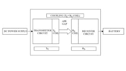
Wireless power transfer systems enable battery charging without a direct wired connection between a conventional charger and the battery. As shown in Fig. 1, a wireless power transfer system consists of two circuits separated by an air gap. Both circuits have a coil associated with them:
- Transmitter circuit with a transmit coil (LX)
- Receiver circuit with a receive coil (RX)
In a typical wireless power transfer system, dc power applied to the transmitter circuit causes the transmit coil to generate an ac magnetic field that induces an ac current in the receive coil, which then powers the receiver circuit that charges the battery. Except for the coupling between the coils and windings this is similar to the interaction between the primary and secondary windings of a transformer. However, coupling coefficient between transmit and receive coils can vary from 0.8 to as low as 0.05, whereas transformer windings can have a coupling coefficient of 0.95 to 1.
A transmitter circuit for wireless power transfer systems is Linear Technology’s LTC4125, a high-performance, monolithic full-bridge resonant driver capable of delivering up to 5W wirelessly to its associated receiver. Housed in a low-profile (0.75mm) 20-pin 4mm x 5mm QFN package with backside metal pad for improved thermal performance, the LTC4125 can operate from Ë40°C to 125°C, in both E and I grades.
In wireless power transfer, the transmit coil must produce a strong enough magnetic field to induce enough ac current in the receive coil. To accomplish this, the LTC4125 employs a series LC resonant circuit with three key features:
- AutoResonant operation that maximizes available receiver power.
- An Optimum Power Search algorithm that maximizes overall wireless power system efficiency.
- Foreign object detection that ensures safe and reliable operation when working in the presence of conductive foreign objects.
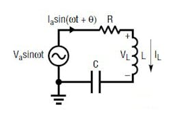
The AutoResonant function is based on a simple series resonant circuit (Fig. 2). When driven with a sinusoid voltage at the resonant frequency the impedance of the inductor and the capacitor cancel leaving a pure resistance, R. The resonant frequency is:
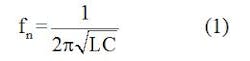
Where:
fn = Resonant frequency
L = Inductance of the transmit coil
C = Capacitance of the transmit coil
At resonance the amplitude of current developed in the inductor is:
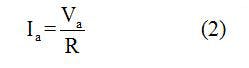
Where:
Ia = Inductor current
Va = Applied voltage
R = Inductor resistance
A low R value allows the circuit to generate a significant amount of inductor current at resonance, where the inductor voltage is proportional to the driving voltage:
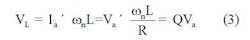
Where:
Q = Quality factor of the series resonant tank circuit
VL = Inductor voltage
wn = Angular resonant frequency
AutoResonant Drive
The LTC4125 enables a series LC to be driven at exactly its resonant frequency. It uses a patent-pending AutoResonant method to automatically detect the resonant frequency of the series LC and drives it at that frequency.
It is easier to generate a square wave than a sine wave, so we will apply a square wave to the series resonant circuit of Fig. 2. With a square wave input, circuit analysis does not change appreciably, assuming the R, L and C values provide a Q greater than 10. Also, frequency selectivity of a high Q circuit ensures that primarily the fundamental component of the square wave affects the voltage and current waveforms across the inductor and the capacitor.
At startup, the LTC4125 drives the LC tank circuit with a 50% duty cycle square wave at 2.5 kHz. After developing current in the LC tank, the LTC4125 detects this condition, and adjusts the frequency of the drive voltage accordingly.
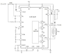
The LTC4125’s AutoResonant Drive employs the SW driver circuit in Fig. 3. It ensures that the voltage at each SW pin is always in phase with the current into the pin. When current flows from SW1 to SW2, switch A and C are on, while D and B are off; and vice versa in reverse.
Locking the driving frequency cycle-by-cycle with this method ensures that LTC4125 always drives the external LC network at its resonant frequency. This is true even with continuously changing variables that affect the resonant frequency of the LC tank, such as temperature and the reflected impedance of a nearby receiver.
AutoResonant switching enables the device to deliver maximum power from a low voltage input supply (3V to 5.5V) to a tuned wireless receiver and battery charger via loosely coupled coils. To optimize system efficiency, the LTC4125 employs a periodic transmit power search and adjusts the transmission power based on the receiver load requirements.The IC stops delivering power in a fault condition, or if it detects foreign object.
In a wireless power transfer system, the transmit coil’s magnetic field must be strong enough to ensure that sufficient power is delivered to the receiver load under the worst coupling condition. However, at the best coupling conditions a strong magnetic field may be inefficient and could damage the receiver. Given dissipative elements in the transmit circuit, transmitting any more power than necessary results in reduced efficiency. Therefore, it is desirable to adjust the strength of the transmit coil’s magnetic field so that just enough power is available to support the load at the receive coil—the optimum transmit power point.
Besides efficiency, there are also safety considerations. A conductive object placed in the magnetic field generated by the transmit coil generates eddy currents in that cause heating due to the object’s resistance. This heating is undesirable for safety reasons, especially in higher-power applications.
Optimum Power Search Operation
Optimum Power Search adjusts transmit power by varying the pulse width of the full-bridge driver (Fig. 3). AutoResonant drive continues to operate as its pulse width is varied to control the amount of transmit coil current. The drive duty cycle is proportional to pulse width. Tank circuit current increases as duty cycle varies from 0% to 50%. Controlling transmit-coil current amplitude is equivalent to controlling the voltage amplitude across the coil at a particular frequency. By adjusting the pulse width of the full bridge driver, the LTC4125 can control both coil current and voltage.
The Optimum Power Search performs a ramp of transmit power at regular intervals, which:
- Detect the presence or absence of a valid receiver
- Detect the presence or absence of a fault condition
- Optimize the transmit power delivery
The linear ramp of transmit power is accomplished through pulse width modulation (PWM) of the full bridge driver one step at a time. This involves the FB (Resonance Feedback Voltage) pin that connects to the center tap point of a resistor divider between the rectified peak voltage generated in the series LC tank and GND (Fig. 3). Shorting the FB pin to GND disables the internal auto load detection feature.
Using the FB pin, the LTC4125 monitors the magnitude of the transmit LC tank voltage at each step. To optimize transmit power delivery, the LTC4125 looks for a large change in peak tank voltage (up or down) from one step to the next. This indicates that the transmit power required to satisfy the receiver load has been met or exceeded.
Once the LTC4125 detects a sufficiently large change in tank voltage the search stops, having found a valid exit condition. The transmit power is held at this level until the next search interval. If the input current exceeds the input current threshold during the power search, then the search stops and the pulse width is held until the next search interval. This is also a valid exit condition. When any valid exit condition is found, the open-drain STAT pin is pulled low to indicate that power is being delivered to the RX coil.
If any of the following conditions are exceeded during power search, the search stops and the pulse width is reduced to zero:
- Temperature threshold as determined by the NTC (negative temperature coefficient) thermistor input
- Maximum tank voltage threshold
- Internal die over temperature threshold
- Frequency threshold (for a foreign object)
- Input current limit (ILIM)
With the pulse width reduced to zero, no power is delivered until the next search interval. When these fault conditions occur, the STAT pin becomes high impedance to indicate that no power is being delivered to the RX coil.
Foreign Object Detection
Simplifying the wireless power system, transmit power optimization, and foreign-object detection features in the LTC4125 does not require direct communication between the transmitter and receiver circuits. Without digital communication the LTC4125 can work over a wide range of transmit-to-receive coil-coupling factors and avoid the need for complicated signal processing hardware and software to support the communication protocol.
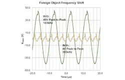
The Frequency Threshold Input (FTH) pin programs the primary protection feature against inadvertently transmitting power into a foreign object. A resistor divider consisting of Ra and Rb connected to the FTH pin (Fig. 3) sets the maximum expected transmit LC resonant frequency. A resonant driving frequency exceeding this programmed value indicates the presence of a large conductive object in the field space generated by the transmit coil. When a foreign conductive object is brought close to the transmit coil, the apparent inductance of the transmit coil dramatically reduces, causing the LTC4125 to adjust its driving frequency higher.
Figure 4 contrasts the tank voltage frequency with and without the presence of a small conductive foreign object. Transmitting into a foreign conductive object may result in transmit power overload and/or excessive heating of the foreign object. If a frequency fault is detected, power delivery stops immediately until the next transmit power search.
If the FTH pin was not frequency-limited, pulses of power would continue to deliver a limited amount of power to the foreign object. To eliminate even this small amount of transmitted power, program the FTH pin (with Ra and Rb) to about 10% to 15% higher than the expected resonant frequency (as determined by the tank inductance and capacitance). Then, if this frequency limit is exceeded at any point during the search interval (typically at the first step), the LTC4125 will stop delivering power to the object and the STAT pin will be set to high impedance to indicate that the transmit coil is not delivering any power. The STAT pin pulls low when the LTC4125 delivers power.
If the FTH pin is not programmed (tied to VIN), the LTC4125 does not detect a valid receiver circuit, and therefore limits the power delivered to a foreign object to only pulses of power that are generated during a search interval. Without a valid receiver, the search fails to find a valid exit condition until it reaches the end of the power search ramp fault condition, which causes the transmitter to stop delivering power before the next search interval.
Programmable maximum current limit and NTC input are additional means of foreign object and overload protection.
About the Author

Sam Davis
Sam Davis was the editor-in-chief of Power Electronics Technology magazine and website that is now part of Electronic Design. He has 18 years experience in electronic engineering design and management, six years in public relations and 25 years as a trade press editor. He holds a BSEE from Case-Western Reserve University, and did graduate work at the same school and UCLA. Sam was the editor for PCIM, the predecessor to Power Electronics Technology, from 1984 to 2004. His engineering experience includes circuit and system design for Litton Systems, Bunker-Ramo, Rocketdyne, and Clevite Corporation.. Design tasks included analog circuits, display systems, power supplies, underwater ordnance systems, and test systems. He also served as a program manager for a Litton Systems Navy program.
Sam is the author of Computer Data Displays, a book published by Prentice-Hall in the U.S. and Japan in 1969. He is also a recipient of the Jesse Neal Award for trade press editorial excellence, and has one patent for naval ship construction that simplifies electronic system integration.
You can also check out his Power Electronics blog.
Comment About the Article
To join the conversation, and become an exclusive member of Electronic Design, create an account today!

Leaders relevant to this article: