Stationary Chargers for EVs — When Cost and Performance Matters

More and more electric vehicle (EV) charging points are sprouting up along highways, byways, and driveways. As availability becomes less of an issue, EV owners are starting to look closer at this equipment’s reliability and the energy costs associated with charging. Equipment vendors have to respond.
Purely electric vehicles need to become more convenient for the public to embrace them wholeheartedly. Engineers will have to find ways to extend their range and rapidly charge empty batteries. It takes considerable charging power to deliver that much energy, that fast.

Home stationary chargers’ power is usually limited to the 22 kW dictated by the distribution grids for residential neighborhoods. Commercial charger stations may be connected directly to a public medium-voltage distribution network via a low frequency transformer, which increases power levels to 100 kW and beyond. In this case, more electrical power can mean faster charging.
A stationary charger unit typically consists of the power electronics, control circuitry, communication with the BMS (battery management system), and the user interface. Power electronics, in turn, consist of two parts, PFC (power factor correction) and the dc/dc converter (Fig. 1).
Three-Phase Power Factor Correction
The PFC shapes the charger’s input current so that it is sinusoidal and in phase with the grid voltage. Figure 2 depicts one phase of a three-phase PFC circuit. The ‘A’ in ANPFC stands for advanced, indicating it is an improved variant of the neutral boost PFC (NPFC).

Two semiconductor switches, T13 and T14, control the current. They may be synchronized. T13 and T14 share a common source connection, so this variant requires just one gate driver and one floating power supply.
The voltage between dc+ and GND may range up to 400V, and the sum output voltage between dc+ and dc- up to 800 V.
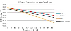
ANPFC’s and SPFC’s switching and static loss are equal, but ANPFC has just one gate-drive circuit (driver IC and supply), so the module and system end up costing less. In fact, ANPC’s efficiency is 15% higher than that of the Vienna rectifier, a well-known and widely used option. Figure 3 compares the efficiency of the SFPC, ANPC, NPFC, and Vienna Rectifier.
DC/DC Converter
The dc/dc converter provides galvanic isolation and adjusts output voltage to battery voltage, which is a function of the state of charge (SOC). An empty battery is charged in three phases starting with constant current, followed by constant power, and ending with constant control of the battery voltage.
Resonant dc/dc converters have been used for years in telecom and server power supplies. Zero voltage switching (ZVS) phase-shifted power converters and LLC resonant converters, for example, both support zero voltage semiconductor turn-on, which helps reduce switching losses and electromagnetic interference (EMI). The LLC resonant converter retains the advantage of ZVS turn-on even under light loads, so efficiency is high under these conditions. This is why engineers have lately acquired a fondness for LLC resonant converters in charging applications.

If the main transformer has a ferrite core, the core and winding work best at a switching frequency of around 130kHz. It is not easy to achieve this high switching frequency with 1200V silicone semiconductor switches at reasonable efficiency. Although 1200V wide band-gap SiC MOSFETs are an option, they are also far more expensive than a standard silicon solution. The second option costs a lot less, which is to use the midpoint of the PFC DC link, with its 400V to dc+ and dc-, and two serial connected half-bridges (H-bridge) with 650V MOSFETs or fast-switching IGBTs. This double H-bridge configuration is shown in Fig. 4.
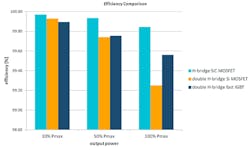
Figure 5 compares an LLC’s module efficiency at light and full load to that of a single H-bridge with 1200V SiC MOSFETs and to that of a double H-bridge with 650V MOSFETs and 650V IGBTs. Figure 6 shows the cost comparison between dc-dc converter modules.
The efficiency of the double H-bridge with 650V fast-switching IGBTs is nearly the same as that of the far more expensive single H-bridge with 1200V SiC MOSFETs.
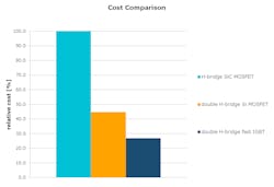
Figure 7 depicts the ANPFC and double H-bridge LLC of a three-phase EV stationary charger. There are at least 20 high-power semiconductors and other discrete components. A heat-sink assembly with discrete components will always offer a lot less design leeway. Compare this with a power module, which has the advantage of a low-inductive configuration with an optimized commutation loop to reduce voltage overshoot and minimize switching losses.
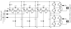
Higher power ratings can be easily achieved by paralleling two or more bare dies inside the module. Add to that a space-saving PCB layout and a simplified mechanical construction. On top of all this, the power module offers a certified and pre-tested insulation system, which guarantees compliance with the relevant regulatory standards.

About the Author
Matthias Tauer
Technical Marketing Manager
Comment About the Article
To join the conversation, and become an exclusive member of Electronic Design, create an account today!

Leaders relevant to this article: