Component Power Analysis Supports Design of 94% Efficient 200 W Supply
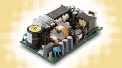
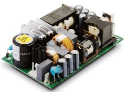
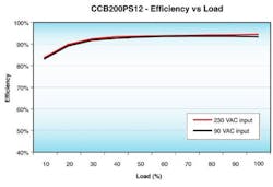
XP Power recently unveiled its CCB200 series of ultra-efficient 200 W single output AC-DC power supplies aimed at medical and industrial applications. Using a detailed power analysis, designers were able to achieve a typical efficiency of 94% and a maximum of 95%, with a flat efficiency curve across the entire operating load range above 20% (Fig. 1).
This new supply follows evolutionary upgrades in previous 200 W supplies. In 2006, the company introduced its 200 W EMA supply with 88% efficiency. Next came the 200 W CCM supply in 2009 with 93% efficiency. Following these previous 200 W power supplies, XP started design of the CCB200 series as its next 200 W ac-dc supply with the goal of 94% efficiency. Requirements for this new supply included:
· Convection cooling, no fan noise
· Ease of integration
· Improved system lifetime
· No derating at 200W full load
· High efficiency / Very low loss
· Compact footprint
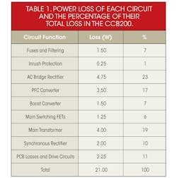
Fig. 2 is a plot of the power supplies efficiency. Achieving efficiency gains above 90% at 90 VAC input were very challenging. Getting higher efficiency, like 95% in loss terms (W), requires the removal of about 55% of the remaining losses. To reach this goal meant that designers had to focus on each small area of loss within the product. Plus, new technologies might have to be required, such as digital control. Table 1 shows the power loss of each circuit and the percentage of their total loss in the new power supply.
Meeting these goals also required careful attention to the power dissipation of every power supply component.
Often overlooked in reliability considerations is the effect of operating temperature on a power supply’s components, notably capacitors. Capacitor reliability, and thus their useful lifetime, depends on their operating temperature, which can be approximated by the Arrhenius' equation, a simple, but accurate formula that relates temperature with reliability, or useful lifetime. A generalization supported by Arrhenius' equation is that, for many common components, their useful lifetime doubles for every 10 °C decrease in operating temperature. Fig. 3 shows how a capacitor’s useful lifetime varies with applied temperature. This also means that a power supply’s operating temperature has a major impact on its capacitors’ reliability, which is also reflected in the supply’s overall reliability.
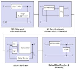
Besides component power considerations, power supply design also required attention to the circuits themselves. Fig. 4 is a block diagram of the power supply. Inrush protection uses traditional low cost negative temperature coefficient (NTC) thermistors. After the start-up phase they are removed from the inrush circuit.
One of the biggest areas of loss in all switch-mode power supplies is the AC bridge rectifier, however they are used due to lack of a cost effective alternative. The current at 90 VAC is tough to deal with and usually results in the need for derating. The bridge rectifier sees this current first hand along with the input filter. Probably 25% of remaining losses come from the bridge rectifier.
The technology employed in the CCB200 ensures the ultra-high efficiency rating is achieved from 90 VAC input, unlike current products in the market that have lower efficiencies at low line and therefore have to specify derating. The full operating input range of the CCB200 series is 80 to 300 VAC, with full power available from 90 to 264 VAC.
To condense the circuitry into the required 3 x 5-in. format and achieve a true 200 W convection-cooled rating it was necessary to increase the efficiency and the input was the obvious area to attack. Bridgeless circuits replacing the diode input bridge with MOSFET’s have become more common in higher power products where the input current is much more of a challenge, so this technique coupled with a discontinuous mode power factor correction (PFC) stage created a low power bridgeless PFC stage that cut the losses in this area from around 4.7 W to around 2 W (a 57% reduction).
Main Converter
The main converter utilizes digital techniques to optimize power transfer, allowing the best lossless transfer regardless of component variations. Coupled with some other careful magnetics design, this technique allowed the absolute maximum performance through the power transformer, reducing its size and allowing the achieved packing density.
Utilization of FETs instead of diodes in the output synchronous rectifier reduces power loss, but equally the PCB layout in the output stage can generate unintended losses especially in lower voltage higher current models. This required careful mechanical routing of these high current paths.
Compared with other 200 W supplies, the CCB200 dissipates 50% less heat at full load, resulting in significantly lower component temperatures and therefore higher reliability and increased product lifetime. High efficiency enables these supplies to be housed in an industry standard 3.0 x 5.0 x 1.43 inches (76.2 x 127.0 x 36.32 mm) package, which usually requires forced-air cooled supplies.
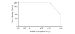
Its high efficiency enables the CCB200 to deliver a full 200 W continuous output power over a Ë20 to +70 °C range without any derating (Fig. 5), and up to +85 °C with derating. The industry high temperature derating norm is typically 20 °C lower (+50 °C) before derating applies.
The CCB200 series conforms to the ANSI/AAMI ES60601-1 medical 3rd edition safety standard and has approval for use in body floating (BF) applications where a patient applied part is used without the need for a further isolation stage. The CCB200 also complies with the internationally recognized UL/EN609501-1 safety standard for IT equipment.
Five models provide popular nominal outputs from + 12 to +48 VDC. A user trim function enables output voltage adjustment of -4 to + 5% of stated nominal in order to accommodate load losses.
Among the CCB200 Specifications are:
· 200 W Convection-Cooled
· Extended Capacitor Lifetime
· No load 0.5 W Input Power
· 47 to 63 Hz input
· Over 0.9 Power Factor
· 5 V/0.5 A standby supply (optional)
· Remote On/Off
· Power Fail Signal
· Overvoltage protection
· Short Circuit Protection
About the Author

Sam Davis
Sam Davis was the editor-in-chief of Power Electronics Technology magazine and website that is now part of Electronic Design. He has 18 years experience in electronic engineering design and management, six years in public relations and 25 years as a trade press editor. He holds a BSEE from Case-Western Reserve University, and did graduate work at the same school and UCLA. Sam was the editor for PCIM, the predecessor to Power Electronics Technology, from 1984 to 2004. His engineering experience includes circuit and system design for Litton Systems, Bunker-Ramo, Rocketdyne, and Clevite Corporation.. Design tasks included analog circuits, display systems, power supplies, underwater ordnance systems, and test systems. He also served as a program manager for a Litton Systems Navy program.
Sam is the author of Computer Data Displays, a book published by Prentice-Hall in the U.S. and Japan in 1969. He is also a recipient of the Jesse Neal Award for trade press editorial excellence, and has one patent for naval ship construction that simplifies electronic system integration.
You can also check out his Power Electronics blog.
