Post-Regulated Fly-Buck Powers Noise-Sensitive Loads
Switch-mode power converter performance requirements dictate high power density and high switching frequency. Plus, there is increasing emphasis on:
· Wide supply voltage range
· Multiple output rails
· Functional safety and galvanic isolation
· Electromagnetic compatibility (EMC), both low-frequency conducted and high-frequency radiated emissions.
This mosaic of requirements sets the basis for robust and proven power converter designs that meet design specifications at package, board, and subsystem levels.
Related Articles
- Synchronous Buck Converter Delivers 12 A With Fast Load Step Response
- UltraFast, 5-A Buck μModule Regulator Cuts Output Noise
- ZVS Buck Regulator Boosts Power In POL Applications
- Selecting BMAX for Ferrite Flyback Transformers
- Voltage/Current Sensing Technique Cuts Flyback Converter Costs
- Protecting Flybacks Against Short Circuits
There are a few inherently-challenging industrial applications such as building and factory automation, PLC I/O modules [1-3], smart e-meters, and interface power for isolated RS-485 and CAN transceivers. Each needs to seamlessly adhere to stringent safety and noise standards, for instance the IEC 61010-1 edition 3 for safety and IEC 61000-4-2/4/5 for ESD/EFT/surge, respectively. Also consider requirements within automotive such as low-noise sensor transducers, insulated-gate bipolar transistor (IGBT) floating gate driver supplies for use in electric power steering (EPS) and braking, and electric vehicle battery management systems (BMS).
Clearly, a “must have” for these circuits is one or more isolated voltage rails. Given this burgeoning demand, the Fly-Buck™ (isolated buck) converter [3,4] is a de facto way to provide low-current auxiliary and bias outputs from a widely-ranging input supply up to 100 V, especially if both isolated and non-isolated rails are required. At the heart of this is the value proposition of the Fly-Buck vis-à-viz conventional flyback or push-pull topologies: simplicity, robustness, and low overall bill-of-materials cost.
Fly-Buck Circuit Implementation
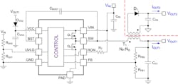
In general, a Fly-Buck solution provides two or more buck-derived outputs. The typical schematic of a Fly-Buck regulator with dual-output configuration is shown in Fig. 1. The isolation barrier is delineated in red.
The main output, designated VOUT1 in Fig. 1, has feedback regulation and is recognized simply as a buck converter output. The slave output, designated VOUT2, referenced to the secondary side is regulated-based on the chosen turns ratio, N = NS/NP, of the transformer, T1. Of course, voltage drops of the powertrain semiconductors and the transformer windings also come into play. Referring to Fig. 1, secondary-side output voltage VOUT2 is given by equation 1, with the transformer winding and MOSFET on-state resistances aptly designated.
Fig. 1. Circuit schematic of a dc-to-dc synchronous Fly-Buck regulator that employs an adaptive on-time control structure to provide primary- and secondary-referenced outputs, VOUT1 and VOUT2.
VOUT2 = N*[VOUT1 + IOUT1*(RPRI + RDS(on)Q2)] – IOUT2*RSEC – VD1 (1)
The power stage incorporates electrical isolation between the primary and secondary sides. Unlike its sister topology – the traditional flyback converter – the Fly-Buck master output is primary-side-referenced and tightly regulated by simple closed-loop feedback. Optocoupler or auxiliary third winding feedback is avoided. Simple control loop architectures that deliver low-quiescent current consumption and fast transient response, like constant on-time control, are well-suited to the Fly-Buck. Conversely, an inherent right-half plane zero generally complicates compensation and transient performance of the flyback.
Output Regulation And Noise
Understanding the circuit and component details of the Fly-Buck is vital to meeting output voltage regulation and noise specifications. For example, transformer leakage inductance accrues as a leading-edge spike on the secondary winding voltage that creates peak charging of the output at light loads, impacting load regulation. Moreover, transformer leakage inductance and parasitic capacitance should be carefully scrutinized to temper noise voltage spikes on the output. Also, as shown by equation 1, cross-regulation depends on transformer winding resistances. The upshot is that a designer must pay close attention to transformer design, component selection, and PCB layout, especially in cost-sensitive applications.
LDO Active Filtering And Post Regulation
Advances in magnetic technology perhaps arguably have not kept pace with developments in integrated power semiconductors. Related to this, active filtering using a low-noise, high-PSRR low dropout (LDO) regulator represents a viable option in place of passive LC or p-stage filters, particularly in low and medium current circuits. Leveraging an LDO as a post-regulator (besides being ultra-small and cost-effective) provides fully-characterized performance parameters, consistent performance over temperature, and less exposure to component and layout parasitics. As such, it is possible to handpick an LDO specifically tailored to the circuit requirements from the broad LDO catalog portfolios typically offered by semiconductor vendors.
The power supply ripple rejection (PSRR) and output noise are critical LDO performance metrics that merit further discussion here. Broadly speaking, PSRR refers to the LDO’s ability to reject its input rail disturbances, whereas output noise arises commensurate with bandgap and other noise sources internal to the LDO.
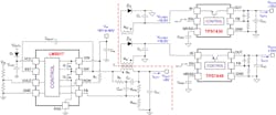
Fig. 2. Fly-Buck multi-output DC/DC regulator with LDO post-regulation of positive and negative supply rails for high-performance analog circuit applications. The LDOs are located adjacent the load for optimal regulation performance.
The PSRR attenuates low-frequency components in applications where passive filtering might otherwise need bulky filter components to achieve low cutoff frequency. As a post-regulator, the LDO’s wide-bandwidth PSRR attenuates the DC/DC converter’s switching frequency ripple and associated harmonics superimposed on its DC output. Such high-frequency components, if not adequately filtered, possibly degrade performance in precision analog and signal-chain circuits. For example, clean voltage rails are imperative in instrumentation applications to maximize detectable signal capture or for increasing dynamic signal integrity and precision. Another example relates to audio applications that are extremely sensitive to distortion or noise in the audio band, 20 Hz to 20 kHz.
Fly-Buck Converter With LDO Bipolar Outputs
In practice, an LDO dovetails quite seamlessly with a Fly-Buck output for tighter voltage regulation and to curtail switch-mode voltage noise. The LDO is chosen to enhance the output voltage load/line/temperature regulation, load transient response, and output noise performance of the Fly-Buck converter, yet keep the dropout voltage to a minimum to reduce power loss. Fortunately, many of the granular control and protection features of an LDO often fall through as accretive to the Fly-Buck’s system-level performance. Examples of this include secondary-referenced enable for ON/OFF functionality, power good flag for sequencing, capacitor-programmable soft-start to smoothly charge large capacitive loads, along with current limit and thermal shutdown protection functions to mitigate transformer overload or saturation. Note that as a Fly-Buck’s secondary-referenced output voltage mainly hinges on the selected transformer turns ratio, post-regulation offers an easy way to fine-tune an output to a target voltage setpoint.
Fig. 2 identifies a 300 kHz Fly-Buck solution with wide input voltage range and LDO post-regulated positive and negative 15 V slave outputs. The LM5017 synchronous DC/DC regulator from TI is rated for 600 mA continuous current across a wide input voltage range up to 100 V [3]. It is available in 4 mm x 4 mm WSON-8 and equivalent SO-8 packages.
The slave outputs in Fig. 2 are post-regulated by positive- and negative-output LDOs, respectively [5]. Both LDOs provide 1.5% DC accuracy over line and load. AC performance is denoted in terms of: 1) PSRR greater than 40 dB up to 1 MHz; and 2) spectral output noise less than 20 mVrms (across standard integration bandwidth of 10 Hz to 100 kHz). As such, these are ideal for powering high-accuracy, high-precision analog designs such as bipolar amplifiers and transducers, RF circuits, and data converters.
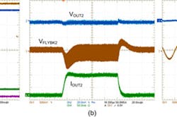
Fig. 3. Fly-Buck performance waveforms at VIN = 24 V: startup (a); +15 V output load transient response (b); +15 V output voltage ripple (c).
Experimental results
The scope waveforms presented in Fig. 3a validate the startup behavior of the 15 V bipolar outputs from a 24 V supply rail. Fig. 3b–3c show the load transient response from zero to 100 mA, and the output noise waveform at 50 mA (pre- and post-regulation), respectively.
References
1. 12-bit, 8-channel, integrated analog input module for programmable logic controllers (PLC), Reference Design (TIDA-00119), Texas Instruments.
2. PLC I/O module front-end controller using a Tiva C series ARM Cortex-M4 MCU, Reference Design (TIDA-00123), Texas Instruments.
3. Powering PLC I/O Module with LM5017 Fly-Buck, TI PowerLab Reference Design (PMP7993.1), Texas Instruments
4. Vijay Choudhary, When is a Fly-Buck the right choice for your isolated power needs?, TI Power House, July 24, 2014.
5. TPS7A49 (150 mA) and TPS7A30 (–200 mA) Low Noise, High PSRR LDOs, Texas Instruments
6. LM5017 datasheet


