Battery Simulator Provides Mobile Insurance
Battery-powered, mobile systems rely on their batteries and battery chargers for reliable operation. Unfortunately, use of the actual battery makes it difficult for design engineers to perform a comprehensive check of the system’s operation with the battery and its charger. Coming to the designer’s rescue is the battery simulator that replaces the actual battery for testing purposes. This simulator can be both a time saver and an essential performance tester during system development as well as production.
Typical batteries used for today’s mobile products are lithium-ion (li-ion), lithium-iron phosphate, lithium-polymer, nickel metal hydride (NiMH), nickel cadmium (NiCd), and lead-acid. Rechargeable li-ion batteries are now the most widely used because they produce more power for their weight (high energy density).
A battery simulator supplies the required voltage, power, and current to the system under test with no apparent difference between the actual battery and simulator. A full-function simulator can seamlessly source and sink current, handling the transition from sink to source without any glitches, even at high speed.
A full-function battery simulator can:
- Adjust its output to source the exact battery voltage and current applied to the mobile system load.
- Set its output in a few seconds compared with the time it might take to charge the actual battery to its fully charged voltage (assuming the actual battery was initially discharged).
- Sink current, which allows it to check operation of the battery charger.
- Simulate the internal series resistance of the battery to see how the system reacts to it.
- Simulate battery noise to see how the system reacts to it.
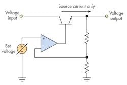
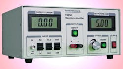
A full-function battery simulator is actually a power supply that can sink and source current. It employs a type of power supply called two-quadrant or four-quadrant (if voltage is negative). In contrast, a conventional power supply can only source current, not sink current. The standard source-only power supply uses just one output transistor designed for sourcing current (Fig. 1).The battery simulator (Fig. 2) has two output power transistors: one for sourcing and one for sinking current. And, it can rapidly transition from sink to source current without producing a glitch.
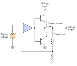
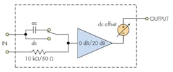
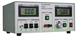
Figure 3 is the equivalent circuit of the TS250 Waveform Amplifier shown in Fig. 4. The TS250 has the features required for a battery simulator. It can sink and source current the same way a real battery does. Its dc offset control adjusts the output voltage, which emulates battery voltage changes. Input impedance can be either 1kΩ or 50Ω, which achieves the lowest noise. Selectable gain is either 0dB or 20dB. Fault protections are: output over-current, input over-voltage, over-heating (thermal), and under voltage. Because the TS250 is a high current amplifier, it can also be used to generate battery noise such as ripple and transient voltage spikes. The TS250 comes with an America-style power cord and accepts universal ac power input from 100VAC to 240VAC 50/60Hz.
The battery simulator can evaluate performance of battery chargers to make sure they are reliable and can properly recharge batteries. It may take considerable time to deplete a battery to allow evaluation of its associated charger, but a simulator can emulate a drained battery voltage within seconds. Without a long wait, a full-function battery simulator can test whether a charger behaves properly and meets its specifications. A battery simulator can mimic an overcharged battery or even an incorrect battery model. If there is a system malfunction, a battery simulator can easily produce the battery voltage from high to low and back and forth to locate the conditions where the failure occurred.
A battery simulator is often used to test the charger operation over the entire battery voltage (0V to 4.2V for li-ion batteries). For example, the li-ion battery normal operating voltage is 3.0V to 4.2V, but battery voltage can be 0V to 3.0V if it is deeply discharged. The charger must be tested to ensure it can charge a battery at any voltage within a limit. Using a battery simulator, you can simulate the battery to any voltage by merely adjusting the output voltage control. You can measure the charging current at low battery voltage, less than 3V for an li-ion battery, normal voltage 3V to ~4.2V, and high voltage greater than 4.2V to verify its full-charged output.
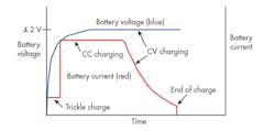
For example, an Li-ion battery typically employs a CC/CV (constant current, constant voltage) charging method. At low battery voltage, less than 3.0V, the battery is trickle-charged at a low current (one-tenth of the normal charge current). Between 3.0V and ~4.2V is the normal rapid charge current. When battery voltage reaches 4.2V, it enters constant voltage mode where the battery voltage is held constant, but the charging current is slowly reduced. Figure 5 shows a detailed CC/CV li-on battery charging profile. Using the simulator, the test engineer can record the current and voltage on a regular interval. For example, he should record the current and voltage every 30 second for the first 10 minutes and every 5 minutes for the remainder of the charging cycle.
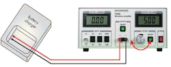
As shown in Fig. 6, the TS250 battery simulator output is attached to the mobile system’s battery connectors. The simulator is replaces the battery pack. For charger testing, change the dc offset control to adjust the emulated battery voltage while measuring the charging current. Changing the battery simulator output voltage from low to high and back and forth shows how the charger reacts to the changes.
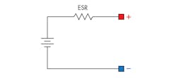
A full-function battery simulator can simulate active battery internal resistance or ESR (equivalent series resistance). Battery ESR is dynamic (non-static) and depends on frequency. As illustrated in Fig. 7, ESR is modeled as resistor in series with a battery. Furthermore, ESR changes with battery capacity, state of charge, chemistry, temperature, age, plus more. A simulator can easily adjust these characteristics to mimic various types of batteries and capacity, as well as mimicking battery temperature. Simulator settings can artificially change the apparent health of a battery, in terms of temperature, size, etc.
Cell-Balancing Testing
Another essential use of battery simulator is to emulate a series-connected battery cells within a battery pack. Many medium-power portable products utilize multiple battery cells connected in series in a battery pack. Normally these batteries are lithium-ion or lithium-polymer. Frequent configurations are two, three, four, and six batteries in series. Connecting batteries in series raises the system’s input voltage and provide electrical power more effectively. Due to voltage output variations from one battery to the next, all the battery cells in a pack may not be at exactly the same voltage. And, sometimes one or more of the batteries may be worn out or defective. When charging series-connected cells, some battery cells might be overcharged, while others are undercharged. Without battery-cell balancing, the designer may deliberately undercharge the battery pack to keep from overcharging any of the cells. Thus, battery-cell balancing is necessary to obtain the maximum battery capacity as well as maintaining battery pack safety.

As illustrated in Fig. 8, whenever one of the batteries is approaching 100 percent charged, the active cell-balancing circuit channels a portion of the current away from that battery while maintaining large charging current for the two undercharged batteries. While the battery is nearing fully charged, the charging current continues to cut back. This process is maintained until all three of them are completely charged.
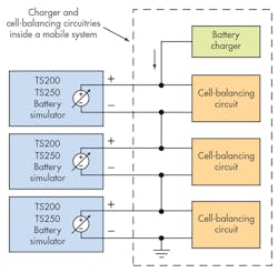
The balancing circuitry and the charger must be sufficiently evaluated throughout the design phase. To test the cell-balancing circuit requires at least one battery simulator. Test technicians can recreate a number of scenarios where that battery is out of balance to observe how the cell-balancing circuits respond. As displayed in Fig. 9, every simulator can adjust its voltage individually. By doing this, it is very easy to change each simulated battery voltage to replicate a battery that is either undercharged, full, overcharged, depleted, or damaged. Design engineers can simply simulate any combination of the above-mentioned battery scenarios (100% charged, overcharged, undercharged, or damaged) to stress test both charger and the cell-balancing circuit.
The TS250 also has built-in current monitor. If the simulated battery is overcharged (>4.2V, which should not happen normally), there should be no charging current to that battery. Other batteries may still be charged normally. If one of the simulated batteries is below the safe voltage limit (less than 3V for example), the balancing circuit may either prevent the charger from starting fast charging (staying in trickle charge, low current) or prevent high-charging current to that battery. This depends on the charging system design that could include several different behaviors and outputs. All of the behaviors should be tested.
About the Author
K.C. Yang
Product Marketing Engineer
Comment About the Article
To join the conversation, and become an exclusive member of Electronic Design, create an account today!

Leaders relevant to this article: