Hysteretic-Mode Converters Demystified, Part 1
Many textbooks and technical articles explain how those voltage mode (VM)1 and current mode (CM)2 controls work. Not much information exists about HM control, however, even though many newly released SMPS ICs are based on HM control.
This series will compare HM control with well-known VM and CM controls from multiple technical viewpoints. The intent is to provide a big picture of HM converters, bridging the gaps in existing HM control resources.
Evolution of Voltage Regulators
Let’s first review an evolution chart of voltage regulators, especially those that are step-down (input voltage > output voltage) (Fig. 1). While it may not represent history accurately, Fig. 1 illustrates technical trends and the similarity of each node.
Within each major branch of linear regulator (LDO) and switching regulator shown in Fig. 1, lower-side-node LDO and HM adaptive Ton are the newer, mainstream technologies. In the switching-regulator branch, the oldest technology is not shown: the HM bang-bang control node.
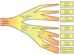
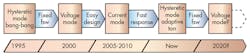
Figure 2 shows generations of step-down switching regulators in roughly five-year increments. Bang-bang control was the first generation of switching regulators. When switching regulators spread out into applications like personal computers and cellphones in 1995, bang-bang control became very popular. Eventually, bang-bang control was replaced by VM, which became popular around 2000 because of its more predictable behavior (thanks to a fixed-frequency operation). CM took over the mainstream position around 2005 to 2010 because of its easy-to-design characteristics—more so than VM. Finally, HM adaptive ON-time control is currently the most popular switching regulator because of its simplicity and fast response over CM. This is a second turn of HM at the mainstream, improved with the latest technologies from the VM and CM eras. It is interesting to note that very recent higher-end performance products have started reusing VM which could be a second turn of VM.
Basics of Step-Down Converters
As shown in Fig. 3, regardless of their control modes, a step-down converter consists of three blocks:
- A modulator block that generates pulse sequences of its input voltage as a high level (A), and the ground voltage as low-level signals.
- An LC filter block that averages out a pulse sequence from the modulator of 1.
- A feedback and loop-compensation block that generates a control signal, VC, by comparing its output voltage with its reference voltage.
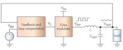
To compare an HM converter with VM or CM converters, Fig. 3 shows a pulse modulator, not a pulse-width modulator (PWM). If the LC filter converts a pulse sequence from this pulse-modulator block to a proper output voltage, this pulse sequence does not have to be a PWM steam. With a HM converter, its sequence is a kind of pulse-frequency modulation (PFM). I’ll examine this further in subsequent sections.
Stable Condition of Step-Down Converter
In Fig. 3, an LC filter block is averaging the high/low density of the VSW waveform: the result is VOUT. Figure 4 illustrates the relationship between VSW and VOUT, where the pulse density of VSW is converted into VOUT. Figure 4 shows four different simulation runs. When using PWM control in VM or CM, this density is called duty cycle, as shown in Equation 1.
D × VIN = VOUT (1)
Where:
D = Duty cycle
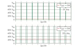
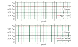
In the case of HM devices, D represents the density of a pulse sequence. Even though in almost all cases, D stands for duty cycle and implies the use of a PWM. In the rest of this series, the symbol D will be used for all control modes, including HM cases, unless it makes a critical difference to explain HM systems. All step-down converters are working at a condition of Equation 1, regardless of control method.
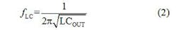
Switching Frequency and LC Filter
To make a step-down converter work, it is essential to maintain the switching frequency, fSW, well above the cutoff frequency point of its LC filter, fLC:
Otherwise, the pulse sequence is not well averaged, which results in a huge ripple waveform at its output voltage. The usual recommendation is to set fSW at least 10 times faster than fLC; 50 times is a good guideline, as shown in Equation 3:
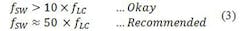
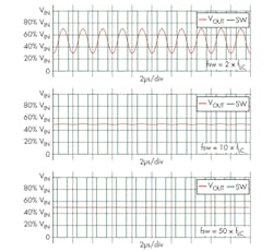
Figure 5 shows the difference between fSW and fLC with simple simulations. These simulations use an LC pair with 1µH inductance and a 10µF capacitor that has fLC = 50 kHz; the switching duty cycle is controlled at 50%. Apparently, the 2 × fLC curve (fSW = 100 kHz) is not regulating its output. The 10 × fLC curve (fSW = 500 kHz) is barely regulating the output, but shows visible ripple in this scale. The 50 × fLC curve (fSW = 2.5 MHz) shows invisible ripple and the output is well regulating.
Perturbation on PWM and PFM
When designing a voltage-regulator system represented by Fig. 3, you can change or shift these major parameters during regulating operation:
- Input voltage, VIN
- Output current, IOUT
- Ambient temperature, TA
The impact of VIN is obvious from Equation 1: VOUT changes proportional to VIN. When VIN changes the regulator needs to adjust its density, D. The third parameter, TA, changes all temperature-dependent system parameters, and the result of TA change can vary significantly. Nailing down details is out of the scope of this article, but keep in mind that any change to TA makes VOUT go up or down.
The second parameter, IOUT, is a little bit tricky in a step-down converter system. Equation 1 is free from any current parameter, which means that the converter is not a function of IOUT in its stable operation. The ideal simulation results of Figs. 4 and 5 show no differences with different inductor dc current values, for example, at 0 A, 1 A, 10 A—even 100 A. When a load-current value changes (load block, Fig. 3), IOUT is a perturbation of the system, which is usually called load transient. Increasing IOUT reduces the output voltage; decreasing IOUT pushes up the output.
Thus, any system-parameter perturbation results in a change of output voltage. The main purpose of a voltage regulator is to adjust its output voltage to stay at a target value. To achieve this goal, the pulse-modulator block changes its output-pulse density: temporary higher density pushes the output up, while temporary lower density reduces the output down.
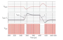
Because VM and CM are systems with fixed switching frequencies, this voltage adjustment action is a change of PWM duty. Figure 6 shows an ideal simulation result showing how duty change follows IOUT perturbation. When IOUT starts increasing (at 550 µs), VOUT starts dropping, as the charge stored in COUT is supporting the IOUT demand increase. In response, the PWM block increases its pulse duty to set target VOUT temporarily higher. Eventually, this undershoot gets to its bottom when inductor current, IL, and output current, IOUT, are equal (at a dotted line around 560 µs). As the dc current of the coil increases further, the excess current (IL - IOUT) charges back the output capacitor, which means that the output voltage starts recovering to its target value. Meanwhile, the duty comes back to its stable condition (period of 570 µs to 600 µs). At 600 µs, IOUT starts decreasing to temporarily set the duty lower. As this VM simulation model supports both 0% duty and 100% duty operations, there’s no pulse placed at the periods between 550 us to 560 us and between 600 µs to 610 µs.
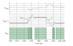
At a perturbation event, an adaptive constant ON time HM converter cannot change its ON period because it is a constant ON time control. Thus, the HM device changes its switching frequency to adjust the output voltage. Figure 7 shows an ideal simulation result. The behavior of the HM converter is almost the same as the previous VM example in Fig. 6; the only difference is that the switching frequency is changing, rather than changing the pulse duty. In Fig. 7, the switching frequency goes higher and pulse density increases at around 550 µs and 620 µs. This 550-µs region is different from Fig. 6, which shows a constant frequency of a higher-duty pulse.
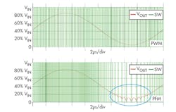
The different simulation results in Figs. 8a and 8b illustrate that both PWM and PFM modulations can generate the same output voltage in a macro view for sinusoidal smooth duty or density changes. Although the two results look like identical waveforms, Fig. 8a consists of PWM where a pulse width is changing, while Fig. 8b consists of constant ON time pulses with its frequency changing. Because of the constant frequency, Fig. 8a shows a consistent green plot line, but Fig. 8b clearly shows a change of density as the frequency changes. Also, in a low-frequency region circled in Fig. 8b, the curve is hitting the LC filter limit shown in Fig. 5, which results in LC ringing on its output waveform.
Part 2 will compare actual transient response waveforms of sample VM/CM/HM devices and review the fast transient response of a HM regulator in detail.
Stability of Step-Down Converters and LC Filters
Common facts in VM/CM/HM
Step-down converters of all kinds oscillate in this sequence unless you perform proper loop compensation:
- The pulse modulator outputs a sequence of pulses, VSW
- The inductor, L, has a 90-deg. phase shift from voltage, VSW, to current, IL
- The output capacitor, COUT, has a 90-deg. phase shift from current, IL, to voltage, VCOUT
- The voltage-feedback signal goes into a negative (180-deg. shift) input of the error-amplifier block
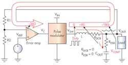
Following the above sequence, Fig. 9 shows a 360-deg. shift in an oscillation. So all control modes provide a loop-compensation scheme to avoid this 360-deg. shift situation. Different control modes use different loop-compensation schemes, which will be in the subsections below.
Part 3 will review the stability of a step-down converter in depth.
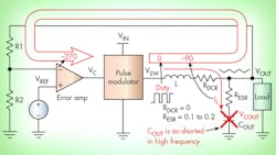
Old and Ultimate Compensation
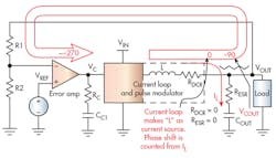
Many engineers remember that loop compensation became a priority when ceramic capacitors rose in popularity. It is also true that, before the ceramic capacitor era, using electrolytic or tantalum capacitors offered a good bonus of higher equivalent series resistance (ESR). With certain higher ESR values, the output capacitor, COUT, turns into a resistor (= ESR) at its resonant frequency, as expressed in Equation 4:
When fCOUT is lower than the control-loop bandwidth, the output LC filter of the converter becomes a pair of inductor (L) and resistance (R), not an LC, which only shifts 90 deg. After combining it with the negative-input terminal effect, the total phase shift still does not hit –360 deg. and the system doesn’t oscillate.
For example, a 47µF capacitor with 0.2Ω ESR has a resonant frequency of 17 kHz, which is reasonably low compared to the frequency bandwidth of many regulators.
A different way to look at this situation is that the inductor current, IL, is monitored by a sense resistor, RESR, when COUT becomes AC-short. As a very rough categorization, this is an extended variation of CM.
Even though ceramic capacitors are used in production, this is a good circuit debugging technique to use with higher ESR capacitors.
VM, CM, and HM Compensation
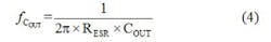
VM compensation
A type-III compensation3 network scheme is widely used to stabilize VM converters (Fig. 11). In short, type-III compensation is an artificial tweak the VM converter feedback signal based on control-loop theories. By using gain from the error amplifier, this type-III network rewinds phase of the feedback signal to avoid a positive feedback situation.
As shown in Fig. 11, a type-III compensation network is fairly complex, as is the component value design.
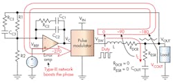
CM compensation
Many CM converters employ type-II compensation4 (Fig. 12). The key concept of CM control is to eliminate a 90° shift at the inductor current by having an inner-current loop in the current loop and pulse-modulator block. When the current loop is closed and working, the inductor becomes a current source and the total loop will not hit a 360-deg. shift.
HM compensation
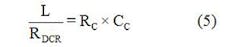
Hysteretic-mode converters are usually compensated with a configuration called a ripple-injection circuit (Fig. 13a). The concept of a ripple-injection circuit is based on the matched dc resistance (DCR) inductor current-sensing method shown in Fig. 13b. In Fig. 13b, a voltage across CS is proportional to the inductor current when meeting Equation 5:
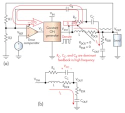
In Fig. 13a, it is not necessary to keep Equation 5, but the essence of the ripple-injection circuit is to obtain inductor-current information and feed it into the feedback signal. Just like in Fig. 10, the ripple-injection circuit is using inductor-current information for stability. This is another largely extended variation of CM.
References
- Daniel Meeks. Loop stability analysis of voltage mode buck regulator with different output capacitor types – continuous and discontinuous modes, Texas Instruments Application Report (SLVA301), April 2008.
- Timothy Hegarty. Current-Mode control stability analysis for DC/DC converters (Part 1), How2Power, June 2014.
-
SW Lee, Demystifying Type II and Type III Compensators Using Op-Amp and OTA for DC/DC Converters, Texas Instruments Application Report (SLVA662), July 2014.
-
Ning Tang, Designing Ultrafast Loop Response With Type-III Compensation for Current Mode Step-Down Converters, Texas Instruments Application Report (SLVA352A), September 2010.
Looking for parts? Go to SourceESB.
About the Author
Masashi Nogawa is a senior systems engineer for Texas Instruments’ Power Management group, where he is responsible for the SWIFT product line. Masashi received his bachelor’s and master’s degrees in electrical engineering from the University of Electro-Communications, Tokyo, and he holds six U.S. patents. Masashi can be reached at [email protected].
About the Author
Masashi Nogawa
Senior Systems Engineer
Comment About the Article
To join the conversation, and become an exclusive member of Electronic Design, create an account today!

Leaders relevant to this article: