IGBTs: Frequently Asked Questions (FAQs)

What is an IGBT?
The insulated-gate bipolar transistor (IGBT) is essentially a three-terminal power semiconductor device typically used as an electronic switch in a wide range of applications. The IGBT combines the simple gate-drive characteristics of the MOSFET with the high-current and low-saturation-voltage capability of the bipolar transistor in a single device. While specific IGBT datasheets and application notes from manufacturers provide a wealth of useful information, navigating this content can be time consuming, particularly for circuit designers new to IGBTs. Fig. 1 shows the cross section, equivalent circuit and symbol for an IGBT.

Related Articles
- Driving And Protecting IGBTs In Inverter Applications
- Expanded IGBT Portfolio
- Rugged, Reliable 600V Trench Ultrafast IGBTs
- 1200-V IGBTs Deliver High Power Density
- 600V IGBTs Increase Power Density, Meet Stringent Energy Guidelines
- Ultrafast IGBTs boost efficiency in appliance motor drives
What are the differences (if any) in the gate drive requirements of an IGBT vs. a similarly rated power MOSFET?
In general, the gate-drive requirements of an IGBT are quite similar to that of a comparable voltage and current rated power MOSFET. This follows from the fact that both these devices have a MOS- (metal-oxide-semiconductor) type gate structure. However, there are a few key differences in terms of their gate drive requirements as noted below:
· IGBTs typically have a higher gate-emitter threshold voltage compared to a MOSFET. Also, at elevated temperatures, a higher gate-emitter voltage is required to ensure the device remains in saturation at a given collector current. For both of these reasons, the IGBT’s applied VGE (gate-emitter voltage) should be at least 14 V (preferably 15 V). In case of similarly rated MOSFETs, an applied VGS of 10 V (gate-source voltage) is generally sufficient to ensure saturation across temperature and current.
· As the gate-emitter capacitance of a similarly rated IGBT tends to be lower compared to that for a similarly rated MOSFET, the series gate turn-on resistor value is often preferred to be higher compared to that for the MOSFET (often twice, or even higher still). This helps limit the turn-on dv/dt and thus minimize the potential for ringing and resultant EMI.
Can multiple IGBTs be paralleled? What are the key precautions to take in this case?
Many modern day IGBTs, such as the new Renesas G7H IGBTs, have a positive VCE(SAT) vs. junction temperature dependence in their nominal current range. As such, these IGBTs can typically be paralleled if a few basic precautions are taken:
· Devices should be mounted on a common heat sink/copper substrate
· The gate-drive layout is symmetrical (gate-emitter loop lengths are similar for each paralleled IGBT)
· A matching and individual 2 to 4 Ω resistor is placed in series with each device’s gate to minimize the possibility of potential gate-voltage oscillations in one device coupling into another paralleled device.
· The gate driver is strong enough in terms of sourcing and sinking current capability to ensure fast-switching speeds. For example, if there are four paralleled IGBTs, each with a QG (total gate charge
requirement) of 100 nC, and it is constrained that the turn-on time be within, say, 100ns, then the minimum sourcing current capability of the gate-drive circuit needs to be at least:
· Ig_driver_sourcing = (4 x 100 nC)/100 ns = 4 A (peak)
· While the sinking-current capability needs to be high as well, it has relatively less influence on the turn-off time (it impacts the rise of voltage time, but has a lesser impact on the fall of the current time).
· It is generally recommended to parallel devices from the same wafer lot (same lot code) to ensure minimum variation across the key parameters of gate-emitter threshold voltage and VCE(SAT).
· In case of any questions, it is always best to contact the IGBT manufacturer for advice.
Can an IGBT be used in synchronous rectifier mode?
No. The IGBT cannot conduct current in the reverse direction (from emitter to collector) even with a positive Vge applied to it, because it has a bipolar-type structure. This is unlike a power MOSFET, which is a unipolar device and hence can conduct bi-directional current, in either direction (drain to source or source to drain), as long as the Vgs > Vgsth is applied?. In addition, power MOSFETs almost always has an intrinsic diode built into their structure from source to drain, which provides a natural path for reverse current flow. IGBTs typically do not have such an intrinsic diode built into their structure (exceptions are the so-called Reverse Conduction IGBTs, which embed N+ regions at the collector to effectively create a P-N diode from emitter to collector). Therefore, in most applications where the load is inductive in nature and there is a requirement to conduct current in the reverse direction (from emitter to collector), a fast recovery diode is connected in anti-parallel with the IGBT (with its anode at the emitter and cathode at the collector). This ensures there is a path available for the reverse current flow. However, the gate has no control over this reverse current flow; it is simply the forward biasing of the diode that allows it.
Do IGBTs require a negative gate-drive voltage to ensure turn off or to hold the device off?
Modern trench gate depletion stop-type IGBTs have excellent noise immunity (in terms of being able to withstand capability to a high dv/dt event at the collector) and work well with 0 to +15 V gate drive signals (VGE = 0 V ensures device turn off and hold off). Furthermore, many modern day gate drivers have relatively low-output impedance and help tie the gate tightly to the emitter when the device is in the off state. As a result, in many applications, such as appliance motor drives, there is essentially no requirement for a negative gate-emitter voltage to be applied to turn-off or hold-off the IGBT. However, in some industrial applications, where the environment is relatively noisier, it may become necessary to provide a negative gate-emitter voltage (applied VGE voltage swing is -5 to +15 V for example). This helps enable a higher level of dv/dt withstand immunity for the device. A negative gate-emitter applied voltage also helps to discharge the gate-collector capacitance relatively faster at turn-off. This helps lower the turn-off switching loss to a certain extent.
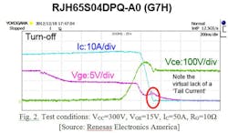
What is the “Tail Current” in reference to an IGBT?
In IGBTs, there is a finite time needed for the minority carriers to re-combine in the drift region even after the applied Vge has reduced below the turn-off threshold. This is particularly pronounced in earlier generation (such as planar gate punch through) technology IGBTs. This additional time required for the re-combination process results in the so-called “tail current” and can be seen on a scope capture of the current waveform at turn off. In contrast, Renesas Electronics’ latest G7H generation high conductivity trench gate IGBTs have a very minimal tail current, enabling a much lower turn-off loss as seen from this example waveform of Fig. 2.
Does an IGBT have a reverse voltage withstand capability?
This depends on the type of the IGBT. NPT (non-punch through) IGBTs can be designed to withstand and block forward and reverse polarity voltages (collector positive, or negative with respect to emitter). These IGBTs are also sometimes called Symmetrical or RB- (reverse blocking) type IGBTs. While NPT IGBTs are capable of very fast turn-off times, they suffer from a relatively higher saturation voltage drop. This has limited their suitability for comparatively higher voltage rated devices (> 1200 V ratings). Today, most commonly used IGBTs in the 600- to 1200 V range are typically Punch-Through (PT) or Depletion or Field-Stop (DS or FS) type. However, these types of IGBTs are typically best suited for and designed to withstand and block a voltage from collector to emitter (collector positive to emitter) only. Such IGBTs are also called Asymmetrical type IGBTs. Typically, such IGBTs have a limited reverse voltage (emitter positive with respect to collector) withstand capability (typically in the few 10s of volts). Also, in these types of IGBTs a reverse voltage withstand capability is not specified on the datasheet. As a result, in any application where load-current commutation is required (such as in most inverters driving inductive loads), there has to be a reverse-connected diode across the IGBT. This ensures the IGBT does not have to withstand any reverse voltage except for a very brief time (few ns) from the application of the reverse voltage until the diode forward biases and conducts the reverse current.
About the Author

Satyavrat Laud
Senior Product Marketing Manager
Satyavrat Laud, senior product marketing manager with Renesas Electronics America, is responsible for product marketing of IGBTs in the Americas. He has more than 15 years of experience with power circuits, systems motors, and devices related to applications, design, and marketing. He received a BS from Mumbai University, India, and an MS in electrical engineering from the University of Houston, Texas.
Comment About the Article
To join the conversation, and become an exclusive member of Electronic Design, create an account today!

Leaders relevant to this article: