Solar Inverters Can Improve Power Quality
A series of tests that were conducted a few years ago were used to characterize typical ”legacy” inverters, including an assessment of their contribution to distortion, anti-islanding issues, and potential aggravated disturbances. Next, test results are presented for an off-the-shelf advanced commercial SPV inverter designed to operate according to recent German grid codes. This inverter has features not presently available in inverters designed according to standards in the United States. This inverter was subjected to various typical voltage and frequency deviations to assess its dynamic performance on the grid. Various standards and technical reports—such as IEC61000-3-15 [2] and the Italian CEI 0-21 [3]—mention the possibility that SPV inverters may be used to improve power quality.
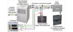
The initial tests on legacy inverters were aimed at verifying that the inverters function safely in accordance with US and international standards. Fig. 1 shows the test setup.
The grid simulator handles bidirectional power flow, just like the electric grid. The inverter is being fed with a DC power supply that simulates the PV panel’s I-V curve. The programmable load provides both linear and non-linear current loads, effectively simulating typical “household load” patterns, such as those produced by PCs, cooking appliances, TVs, air conditioners, etc. The power analyzer provides information on the current flow in the load, as well as into or out of the public supply and the inverter.
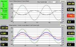
Fig. 2 shows a typical display from the power analyzer.
The top graph shows the voltage (green) and the current (black) flow of the grid simulator, i.e. the electric grid. The bottom graph shows the load current (red) and the inverter current (blue). The inverter delivers 1274.9 Watt to the household (load) and 1766.5 Watt to the grid. A few are lost in the system wiring etc.
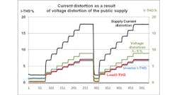
The public supply rarely has such a nice sinusoidal voltage. Voltage distortion of 2 – 5 % V-THD is not uncommon. To evaluate the PV inverter response to a distorted voltage, the grid simulator was programmed in 1% steps to have from 3 - 9 % voltage distortion, at harmonic order 9 (VH9).
As the graph in Fig. 3 shows, the current distortion into the grid is about double the programmed voltage distortion.
This is due to the fact that the inverter “tracks” the supply voltage, i.e. adds about the same amount of current distortion that is already present. If the inverter were to be “permitted” to compensate, it could actually reduce the current distortion into the public supply. Modern inverters have this capability as we will see.
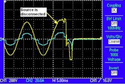
Another undesirable consequence of early requirements placed on PV inverters is their response to voltage dips and short interrupts to avoid “islanding operation.” Standards require that the inverter separate itself from the electric grid within 160 ms in the event that the supply voltage goes outside specified tolerances (usually about ± 10 % from V-nom).
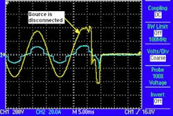
Fig. 4 shows the inverter response to a short voltage dip.
The PV inverter disconnects within 10 ms and remains “off-line” – sometimes for as long as several minutes. Such a response will generally aggravate the “dip” as the power contribution from the inverter “goes away”. It is now recognized that a certain amount of low voltage ride through (LVRT) is much more desirable.
Advanced Solar inverter Capabilities
In order to evaluate how advanced solar inverters may affect the electric grid, Southern California Edison (SCE) acquired several residential and commercial solar PV inverters designed to operate according to German grid codes. These inverters have advanced features not presently available in the inverters with U.S. standards. This section will contain some of the testing of the commercial German inverter tested at SCE DER laboratory.
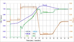
Newer inverter designs permit voltage ride-through capabilities, such as the low voltage ride-through that can be adjusted between 40% and 100% of voltage. When the system voltage is above this lower limit, the inverter continues generating power and DOES NOT disconnect from the electric grid. When the system voltage falls below the lower limit, the inverter ceases generating power to the grid. The inverter can stay connected to the grid for an adjustable time (minimum of 0.04 seconds and maximum of 10 seconds for the unit tested at SCE), but will not export power to the grid until the voltage returns above the lower limit plus a dead-band amount (hysteresis).
Fig. 5 illustrates this capability.
The voltage (blue line) briefly falls below 47 % of V-nom, causing the inverter (green line) to cease generating power, but as soon as the voltage goes back to > 47 % plus the 3 % hysteresis band, the inverter ramps its power back up (just before second # 8). When the public supply voltage exceeds V-nom, at second # 17, the inverter scales back its power contribution, and after the voltage stabilizes at V-nom (second # 27) the inverter resumes full power. This type behavior is much preferred vs. the “traditional response” where the inverter simply disconnects from the grid when the voltage falls below say 90 %, and stays disconnected for several minutes.
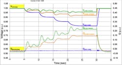
Solar inverters can greatly improve voltage stability in “weak networks” as shown in Fig. 6.
For this test, the grid simulator was set as a “weak source” where its output current was progressively limited in approximately 5 sec intervals. The purpose of this was to decrease the generation-to-load ratio of the test setup so the system voltage steadily drops (as in a weak – rural – system).
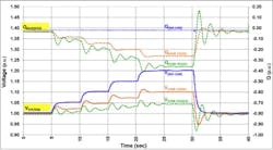
This test allows the assessment of the inverter (VAR) voltage support capabilities. Fig. 6 shows three scenarios: Inverter voltage support turned on at a 3% ramp rate (green plot), voltage support turned on at 1% ramp rate (orange plot), and voltage support turned off (blue plot). When the voltage support is enabled and voltage falls below 98%, shortly after the 5 second mark, the inverter immediately increases its VAR output, raising the system voltage. The data clearly shows the advantages of implementing voltage support on solar PV generation, with the voltage remaining within 5 % of V-nom when voltage support is turned “on”. During over-voltage situations, the inverter can behave in an inverse manner, i.e. reduce the effect of over-voltage (such as happens when loads disconnect). Fig. 7 illustrates this scenario.
Advanced inverters typically have several communication capabilities, via serial and even via Bluetooth interfaces. For both tests – illustrated in Figs.6-7, the inverter was programmed with the following parameters when voltage support was enabled:
- VAR support: maximum of 50% of full power
- Q/V gradient: 0% (NO-VAR), 1%, and 3% (This gradient is the relationship between reactive power and voltage.
Before beginning the test shown in Fig. 7, the grid simulator voltage was set to 120% of nominal voltage, but its output current was limited so that the load was pulling the grid simulator voltage down to the desired nominal value. During the test, the grid simulator output current was progressively increased manually in approximately 5 s intervals.
This simulates the increase in generation-to-load ratio so that the system voltage steadily rises, which in turn permits the assessment of the inverter’s voltage support functions. As with the previous test, Fig. 7 plots three scenarios: voltage support at 3% ramp rate (green plot), at 1% ramp rate (orange plot), and turned off (blue plot). When the voltage increases above 102%, shortly after the 5 second mark, the inverter immediately absorbs VARs from the system, and thus helps to stabilize the system voltage. Obviously, this is much preferred over the situation where the voltage increases substantially (up to 120 % of V-nom in this case) without voltage support turned “on”.
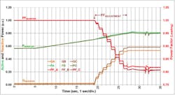
As part of under-and-over voltage support, advanced inverters can adjust their Power factor (PF). This is illustrated in Fig. 8.
The inverter adjusts its PF as a function of power output, in this case from a PF of 1.00 at 60 % output to just over 0.8 at 80 % output.
The results of our tests indicate that certain advanced features could benefit the operation of the grid, if they are incorporated into IEEE 1547 and California Rule 21. Several IEC standard committees, as well as national committees of individual countries that have, or expect to have, the number of solar photovoltaic inverters connected to their grids to increase have already embraced these advanced inverter capabilities. They are, in fact, counting on the improved characteristics to improve power quality in the public supply network.
References
1: B. Yinger, R. Bravo, and R. Salas, “Integration of Large Rooftop PV Arrays in the Distribution System,” San Antonio, TX, Distributech 2012.
2: IEC61000-3-15 Assessment of low frequency electromagnetic immunity and emission requirements for dispersed generation systems in LV networks
3: Reference technical rules for the connection of active and passive users to the LV electrical Utilities (Italy – 2011-12)
