Operating from a single 2.7 V to 5.5 V input, ams (formerly austriamicrosystems) introduced the AS3721 power management IC (PMIC). It employs an innovative remote-feedback circuit that reduces the thermal stress on application processors in smartphones and tablets.
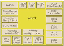
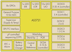
Fig. 1 is a block diagram of the AS3721 that contains three DC-DC controllers requiring an external power stage (DCDC0, DCDC1, and DCDC6) and four DCDC voltage regulators (DCDC2, DCDC3, DCDC4, and DCDC5). Table 1 lists the AS3721’s features.
The DC-DC voltage regulators are high efficiency fixed frequency current mode types. They achieve up to 95% efficiency by using low resistance internal PMOS and NMOS switches. Their fast switching frequency allows use of small inductors, without increasing current ripple. A unique feedback and regulation circuit guarantees optimum load and line regulation over the whole output voltage range, up to an output of 1.5 A for DCDC4 and DCDC5, 2 A for DCDC3 and 4 A for DCDC2, using only an 8-27 µF output capacitor. A current limiter protects each DCDCx voltage regulator.
Related Articles
- Back to Basics: Power Management Impacts All Electronic Systems
- IC Manages Multiple Supplies on a Single Board
- Power Architecture Tackles Power Management Complexity
- Digital Power Management Done Right
Integrated multi-phase controllers DCDC1 and DCDC6 are two-phase types using an external power-stage, like the company’s AS3729. By incorporating two 2.5 A phases, their maximum output is 5 A, which allows use of low profile inductors without compromising performance. You can use controller DCDC6 in a special mode using two 5 A phases and supporting inductors that provide up to 10 A. Multi-phase controller DCDC0 can employ up to four power stages (eight phases) for a maximum 20 A output. And, you can scale its output current by varying the number of phases and power-stages from 2.5 A to 20 A.
When paired with the company’s AS3729 power stage, the AS3721 provides a complete power management system with high efficiency, flexible board layout, and fast response to processor load transients. The AS3729 power stage is housed in a chip-scale package measuring just 1.6 mm x 1.6 mm and with a 0.4 mm pitch.
The AS3721 and AS3729 are optimized for use with Nvidia’s Tegra applications processors. This PMIC enables a compact remote feedback path from the processor to the AS3721’s DC-DC controllers.
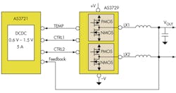
Fig. 2 shows the AS3721-to-3729 interface that requires only two control lines and one temperature signal, instead of the four or five wires typically required by other PMICs. The feedback loop carried over the AS3721 interface operates extremely fast, maintaining the processor it supports within its safe operating voltage even when supplying extremely fast-changing loads. Using an output capacitor of just 40 µF and at an output voltage of 1.0 V, the system’s voltage drop during a step up from 0.5 A to 5 A in burst mode is typically just 32 mV.
With fewer traces connecting the PMIC to the power stages, the AS3721 and AS3729 can be placed farther apart in the board layouts of space-constrained devices such as smartphones, tablets and notebooks. This dramatically reduces the size and intensity of any hotspot around the processor; in contrast with conventional power architectures in which the processor and PMIC, both handle high currents simultaneously, so they must be placed side-by-side.
A serial control interface enables programmable, regulated supply voltages. Operation at 3-4MHz with 1 µH coils reduces cost and PCB space. Multi-phase topology operating at 3 MHz ensures fast load transient responses and reduces external component footprints.
Mode Settings
You can program the voltage regulators to provide:
· Low ripple, low noise
In this mode, there is no minimum coil current necessary before switching off the PMOS. As long as the load current is superior to the ripple current the device operates in continuous mode. When the load current gets lower, it triggers the discontinuous mode. This results in a very low ripple and noise, but decreased efficiency, at light loads, especially at low input to output voltage differences.
· High Efficiency
This mode sets a minimum coil current before switching off the PMOS. Therefore, fewer pulses are necessary at low output loads, which increases output efficiency for low loads. However, this mode increases the ripple at higher output currents.
· Power save
As soon as the output voltage stays above the desired target value for a set time, the AS3721 powers down some internal blocks, leaving the output floating, which lowers power consumption. Normal operation starts as soon as the output drops below the target value for a similar amount of time. To minimize accuracy error some internal circuits remain powered to ensure a minimized output voltage ripple.
· Fast regulation
You can use this mode to react faster on sudden load changes and thus minimize output voltage over/undershoot. This mode needs a bigger output capacitor to guarantee regulator stability.
For very low load conditions, e.g. during a processor sleep mode, you can reduce the switching frequency to achieve a higher efficiency. Normally, the switching frequency for DCDC2, DCDC3, DCDC4 and DCDC5 is 3 or 4MHz.
DC-DC controller mode settings are:
-Low Ripple, Low Noise (similar to voltage regulator)
High Efficiency (default setting similar to voltage regulator)
-Low Power
In this mode the controller runs at a single phase. Only one output stage of the external power stage is used to reduce the power consumption for standby mode operation.
•Power Save (automatically controlled similar to voltage regulator)
•Force PWM Mode Operation
•Load current can get so small that less than the minimum on-time of the PMOS would be needed to keep the loop in regulation. Then, the regulator will still stay on the fixed switching frequency without entering low power mode. This mode guarantees the lowest possible ripple and a fixed frequency over all load conditions, but it compromises efficiency.
•Fast Regulation Mode (similar to voltage regulator)
•DVM (Dynamic Voltage Management)
•You can enable the DVM mode to minimize the over/undershoot during an output voltage change. With DVM the output voltage will ramp up/down with a selectable slope. Without DVM the slew rate of the output voltage is only determined by external components like the inductor and load capacitor as well as load current. You can select DVM for all step-down controllers, but only one at a time.
LDO Regulators
Eleven universal IO range LDOs offer a wide input (1.8 V to 5.5 V) as well as a wide output (0.8 to 3.3 V) range for general purpose peripheral supplies. A twelfth, LDO3, is intended for tracking the output voltage of DCDC1 or DCDC6, step-size and range are matching those of DCDC1 and DCDC6. The extended input range LDO (LDO0) can work down to 1.15 V on the input side, to be used as a post regulator after a DCDC with low output voltage (e.g. 1.2 V). Up to 300 mA possible outputs are possible with good noise and regulation performance and very low quiescent current, even suitable for stand-by power supply.
All LDOs, the DCDC step-ups and DCDC step-downs have integrated over-current protection. Chip over-temperature protection can be switched on with the serial interface signal enabled by default.
Among the other features of the AS3721 is a backup battery charger that operates as a programmable voltage limited current source with a selectable output resistor. Its capabilities include:
• Backup battery presence detection
• Selectable output resistor to reduce the current at higher voltages
• Programmable charge current
• Programmable maximum charging voltage
• Charging stops automatically as soon as the backup battery is fully charged
You can configure each of the AS3721’s has eight GPIO pins as digital input, digital input (with pull-up or pull-down), ADC input (tri-state), push-pull output (selectable lower or higher GPIO supply), or open drain output (with or without pull-up). The GPIO block includes an internal programmable PWM generator you can connect to any of the GPIO outputs.
A watchdog timer is available to detect a software deadlock. If the watchdog is active, it must receive a continuous trigger signal within a programmable time window. If there is no signal anymore for a set time period from a defined pad or special serial interface bit, it starts either a complete reset cycle or initiates the power off sequence.
A general purpose 10-bit ADC can be used for measuring voltage and current. It is used to perform functions like battery monitor, temperature supervision, button press detection, etc.
A real time clock (RTC) module provides time information to the system. It is implemented as a 6-bit counter that is incremented every second - with the 32 kHz oscillator delivering the necessary accurate time base - and is reset to 0 each time the counter value is 60.
There is both an I²C and SPI interface that share the same pins. Therefore, they cannot be used at the same time.
About the Author

Sam Davis
Sam Davis was the editor-in-chief of Power Electronics Technology magazine and website that is now part of Electronic Design. He has 18 years experience in electronic engineering design and management, six years in public relations and 25 years as a trade press editor. He holds a BSEE from Case-Western Reserve University, and did graduate work at the same school and UCLA. Sam was the editor for PCIM, the predecessor to Power Electronics Technology, from 1984 to 2004. His engineering experience includes circuit and system design for Litton Systems, Bunker-Ramo, Rocketdyne, and Clevite Corporation.. Design tasks included analog circuits, display systems, power supplies, underwater ordnance systems, and test systems. He also served as a program manager for a Litton Systems Navy program.
Sam is the author of Computer Data Displays, a book published by Prentice-Hall in the U.S. and Japan in 1969. He is also a recipient of the Jesse Neal Award for trade press editorial excellence, and has one patent for naval ship construction that simplifies electronic system integration.
You can also check out his Power Electronics blog.


