IC Design Goes Green
In today's designs, application-specific integrated circuits (ASIC) and field-programmable gate arrays (FPGA) must dissipate as little power as possible. Low dissipation ICs comply with government efficiency regulations, fulfill customer demand for green products, and meet the need for longer battery life in handheld and mobile devices. ICs that dissipate too much power can also force designers to use a more expensive package.
A number of ideas have sprung up to help electronic-device makers cut power at the IC level. However, these approaches require significant design expertise — which is scarce. It is also problematic to verify these techniques using the manual approach designers rely on out of habit and necessity.
However, high level synthesis (HLS) software is addressing these issues by automating power optimization while providing a quick path from specifications written in C++ to hardware implementation. HLS software gives users a more abstract and therefore easier, faster approach than that of working directly at the register transfer level (RTL).
The register transfer level defines circuit behavior in terms of the flow of signals between hardware registers and the logical operations performed on those signals. Because traditional RTL coding is done manually, designers can create only one version of a design, which may not be optimal in terms of power, area, and performance. High level synthesis software, on the other hand, automates RTL code generation. This lets designers easily create multiple versions of the same design that are functionally identical, but provide a range of options for balancing power, circuit area, and performance — the so-called “primary colors” of electronic design.
Basics of IC Design
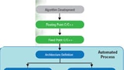
Before looking more closely at HLS tools, it is first helpful to understand the role of “abstraction” in IC design. The higher the level of abstraction, the easier it is for engineers to design, verify, and modify circuit function. As a design moves from original concept to the final IC, the representation becomes more detailed, reflecting the additional decisions and information added to the model description. When automated, this process of transforming the design description to a lower level of abstraction is called “synthesis.”
HLS software such as Mentor Graphic's Catapult C Synthesis tool translates the original design specification, generally written in C++, to a hardware-description language like Verilog or VHDL. The input model for HLS is more abstract than for the RTL in the sense that the source code is a functional description only; there are no timing or concurrence definitions. The HLS model is also technology-neutral; it can be used with any chip technology.
Importantly, HLS tools automatically add the implementation-specific details required to generate the register transfer level view. From there, an RTL synthesis tool produces the collection of networks or gates called the gate-level netlist. The netlist contains the attributes and the “wires” that connect things within the circuit.
Increasing the level of abstraction fosters innovation in digital IC design. RTL techniques were introduced in the early 90s, when telecom and network applications drove chip complexity to unprecedented levels. Back then, designers who switched from working with older methods for defining gate-level processes to working at the RTL vastly boosted their productivity. Today, however, RTL techniques are running out of steam as ICs reach new complexity thresholds. One of the biggest issues with RTL methods is that they were developed two decades ago. At that time, design area and timing were key goals, but power consumption was hardly a consideration. So RTL design methods were not conceived to address power, and RTL designers were not taught to optimize for low power. As a result, power optimization happens as an afterthought in today's flows. Only after the RTL portion is completed can designers go back and figure out clock-gating schemes and other circuit-level approaches to cut power. Needless to say, this approach is error-prone and time-consuming.
A significant recent development in leading-edge high level synthesis software is the capability to automate power optimization techniques, even for dataflows and control domains in extremely complex, multimillion-gate ICs. Among the more advanced tools are clock gating, multiple-clock-domain management, and dynamic voltage and frequency scaling.
Clock Domains and Gating
IC designs are constructed using smaller functional units called blocks, which can run at different clock speeds. Designers use multiple clock domains to drive blocks with the appropriate clock speed. An IC can be designed so the fastest clock drives every block, but that means a lot of unnecessary switching and power dissipation. On the other hand, blocks that run at slower rates can be driven with slower clocks. This means less switching, which translates to lower energy consumption.
The design challenge with multiple clock domains is that should the transfer of data from one domain to another “misfire,” there is a high risk of losing data. Designers use all kinds of specialized devices, including synchronizers, to ensure data behaves correctly as it moves between domains. Designers must use sophisticated verification tools to check for these clock-domain-crossing issues. Multiple power or voltage domains have similar issues, but here designers are driving different types of power between blocks instead of clocks.
Software like Catapult C Synthesis adds the needed synchronizer and lets designers easily explore many design alternatives. For instance, running certain parts of a design at a frequency higher than the data rate can let the design share expensive circuit resources. An automated multi-clock feature in HLS software helps engineers trade-off power, circuit area, and performance for the most efficient design — a task clearly unthinkable to do by hand.
Another power-reduction technique is called clock gating. Here, designers place an “enabler” gate between a particular register and the clock that drives it. This arrangement lets the register be turned on or off independently. This is like turning the lights on only when you are in a room and turning them off when you leave. From a lower-power point-of-view, the best way to do this is to gate all registers individually.
Currently, most designers use a “global enable” command to fully suspend or enable the whole design because of the incredible amount of work it takes to implement clock gating at the register level. To continue the analogy, this is like either having every light in your house on or every light off. HLS software can perform multi-level clock gating, which identifies all clock-gating candidates in a design. In an automated fashion, Catapult analyzes every register in turn, figures out when and how they can be suspended, and builds the proper control logic to drive the enablers. Because it builds all possible clock-gating candidates, whenever a register can be clock gated, the software produces the structure to gate it. This approach optimizes designs' power consumption far better than designers can do by hand. Users see power reductions of anywhere between 40% to 90%.
Frequency and voltage scaling
Dynamic frequency scaling is on the leading edge of low-power design optimization. Like multi-level clock gating, it is a subtle yet powerful way to improve the on-off approach used in global clock gating. The idea is to drive the design with a slower clock than usual for non-critical tasks.
In a digital IC design, the switching power, or dynamic power is measured by
C × V2 × f
where C is capacitance, V is voltage, and f is frequency. Thus, slowing the clock and scaling down the frequency linearly reduces the power consumed. The IC still takes the same number of cycles to perform a task, but each cycle takes longer due to the slower clock. This approach dissipates less energy. Dynamic voltage scaling works much the same way but through voltage management. Power savings in this case follow a geometric progression.
High level synthesis tools are useful here because they provide power-management algorithms to determine when to slow down parts of a design and the high-level knowledge to build the blocks correctly. For example, Catapult C tells the power-management units what the blocks are doing and then lets the designer make the correct decision about how to drive them.
A Balancing Act
Just as there are many ways to skin a cat, a given functionality can be implemented at the RTL in many different ways, with each having a different balance of performance, power, and area. However, RTL designers rarely, if ever, have the time to try out different combinations of these variables. They write one implementation that works, and then they optimize it. Ironically, RTL synthesis tools give an accurate measurement of these three attributes, yet there is not enough time to create and assess more than one RTL netlist. So any optimizations to the RTL remain within the bounds of that initial attempt, even if it is obvious that a different netlist would do better.
In contrast, high level synthesis tools automatically create multiple RTL netlists so designers can analyze a variety of scenarios. HLS can generate dozens of implementations in literally minutes, and each of these solutions has an area, performance, and power value.
A closer look at digital IC design
This kind of design entails:
-
Working on the electronic system level (ESL), where a designer writes the original specification which defines what he wants the chip to do based on criteria for a specific product. To write the spec, engineers can use a variety of languages and tools such as C/C++ or Simulink and Matlab.
-
Next comes converting the specification into a register transfer level (RTL) description. This describes the behavior of the digital circuits on the chip and the connections to I/Os.
-
Lastly, designers combine the RTL description with available logic gates to create a chip design. This involves selecting the proper gates, defining their locations, and wiring them together.
More Info
Mentor Graphics Corp.
www.mentor.com
Demo of the workings of Catalyst C http://www.mentor.com/products/esl/catapult-c
Thomas Bollaert's blog
http://blogs.mentor.com/thomasbollaert
About the Author
Comment About the Article
To join the conversation, and become an exclusive member of Electronic Design, create an account today!

Leaders relevant to this article: