Why Network Analyzer Signal Levels Affect Measurement Results
Find a downloadable version of this story in pdf format at the end of the story.
When measuring a circuit or device with a network analyzer, engineers generally inject a signal and believe that the measured results reflect that of a “small-signal” AC measurement. Many of us have been taught to keep the signals “very small.” But what does that mean exactly? This article will answer the question “how small is very small” and additionally ‘is the reason that the signal must be so small due to an issue with my network analyzer?” We will also discuss why we do not see the effects of signal amplitude in corresponding SPICE simulations.
SPICE-based circuit simulators use partial derivatives to perform small-signal AC analysis; therefore, they are not sensitive to the independent voltage sourceís signal level; regardless of the AC magnitude, the results are linearized and scaled. So, in a physical test environment, how large can the injected signal be before it significantly impacts the measurement?
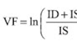
We can start by first characterizing a semiconductor device we want to measure. We will use a transistor as an example because a transistor has a known emission coefficient (N=1), thus removing N as an unknown parameter. The voltage of a silicon junction is given by:
Where:
ID = Forward biased current
IS = Saturation current
N = Emission coefficient
VT = Thermal voltage (K×T/Q) = 0.026V @ 25°C
Rs = Series resistance
Differentiating VF with respect to ID results in the junction impedance:
Where:
Rj = Small signal junction impedance
If we assume the junction temperature of the device to be 25°C, knowing the Boltzmann constant, K, and the elementary charge, Q, we can solve VT as shown by:
We can also assume ID is much greater than IS, and Rj is much greater than Rs; therefore:
Next, we can derive an equation that defines the maximum input power allowed to obtain an impedance result that is within 10% of the exact small signal solution as a function of the DC bias, the signal's source impedance (Rin), and the device emission coefficient:
We know the emission coefficient of a transistor is 1, and our network analyzer source impedance is specified to be 50 Ω, so we can determine the maximum allowable input power level for a range of bias conditions:
Pin_dBm(0.0001,50,1) = -30.69 dBm
Pin_dBm(0. 001,50,1) = -22,47 dBm
Pin_dBm(0.005,50,1) = -11.027 dBm
Pin_dBm(0. 01,50,1) = -5.387dBm
Continue on next page
Next, let's confirm these signal level calculations using the Picotest J2130A DC Bias Injector and an OMICRON Lab Bode 100 network/impedance analyzer connected as shown in Fig. 1. The OMICRON Lab Bode 100 is a low cost, 1Hz-40MHz Vector Network Analyzer capable of measuring gain, phase, complex impedance, group delay and many more functions.
The Picotest DC Bias Injector is part of a complete family of signal injectors. This injector allows a device to be biased using a variable voltage source of -50 to +50VDC, and with a 10kOhm impedance, allows low current biasing of semiconductor junctions as well as measuring DC bias effects of components such as capacitors and varactors.
The output signal level of the Bode 100 is adjustable between -27dBm and +13dBm.
All the cabling and board parasitics are eliminated from the measurement by calibrating the analyzer, in accordance with the Bode 100 user manual, using a standard Open, Short, Load calibration technique. The collector and the base of a 2N3904 transistor are connected together as shown in Fig. 2, and the bias current is set via the DC bias source at 1mA. Two impedance measurements are made at injection levels of -23dBm and -13dBm.
Fig. 3 shows us that the 10% error result of 27.8 ohms is measured with a -23dBm signal level, while the measurement with a -13dBm signal result reflects a 100% error.
Taking this one step further, we can use the harmonic balance (“HB”) engine in the Agilent ADS simulator to confirm the effects of input signal power on the junction impedance. Like a small signal simulation in SPICE, harmonic balance yields a steady-state solution and analyzes the circuit in the frequency domain. Unlike SPICE's small-signal approach, HB uses a large signal solution to model signal effects on all components in the simulation. Fig. 4 shows the ADS HB simulation schematic; Fig. 5 shows the simulation results.
Marker m4 in Fig. 5 shows the operating condition where the impedance deviates 10% from the actual value, which occurs at -23dBm. The simulated impedance is 28 ohms, which agrees with the bench result at that injection level of 27.8 ohms. Moreover, the 54-Ohm impedance obtained with an injection level of -13dBm agrees in both the measurement and the simulation.
By modifying either the bias condition on the device or the source impedance in Equation (5), we can observe a wide range in the allowable input signal levels. Referring to Equation (2), the bias current changes the impedance of the junction. From this equation, IS, N, Rs and to a smaller degree, temperature, can all affect the junction impedance.
The Picotest J2130A DC Bias Injector, combined with the OMICRON Lab Bode 100, can be used to extract all of these junction parameters, and in a similar method to measuring the transistor, we can determine the allowable input signal power for a valid measurement.
The effects of a too-large injection signal can cause serious measurement errors in typical real-life network analyzer measurements such as the Bode plot of a typical series voltage regulator (Fig. 6). Significant errors can be introduced into the Bode plot as a result of an excessive signal level.
Download the story in pdf format here.
Comment About the Article
To join the conversation, and become an exclusive member of Electronic Design, create an account today!

Leaders relevant to this article: