Making The Connection Key To Accurate Test Data
We often give even less thought to how we connect our circuits and systems to the test equipment that we use to power and measure the performance than should. We know this because we frequently see the ramifications in the worst-case circuit analyses that we perform. Here, we will take a look at how the lack of attention to interconnect detail may impact the resulting test data that we obtain.
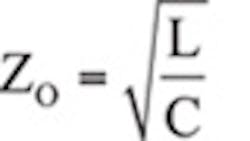
Every connection can be represented by both coupled and uncoupled inductance, resistance and capacitance. These connections can be represented by a characteristic impedance, ZO, defined by:
Where:
C = Capacitance of the connection pair
L = Uncoupled inductance of the connection pair.
We can reduce the uncoupled inductance by twisting the wire pair at the expense of increased capacitance. A connection pair that is terminated into its characteristic impedance appears only resistive and neither inductive or capacitance, resulting in optimum frequency response. Some of the more common controlled impedance connection pairs include Ethernet cable and USB cables (100Ω), cable TV coaxial wire (75Ω), and most RF equipment, including RF test equipment (50Ω).
The inductance, capacitance and resistance of the interconnect wire pairs can be measured using a vector network analyzer (VNA) in a single port reflection measurement. A frequency response analyzer (FRA) generally cannot make the measurement using this method, but it is possible using an impedance adapter.
Fig. 1 shows a connection diagram for the single port measurement. A Short-Open-Load (SOL) calibration is performed prior to making any measurements in order to remove any unwanted board or cabling parasitics. The capacitance is measured with the far end of the cable pair open, while the inductance and resistance of the cable pair are measured with the far end shorted.
A selection of interconnecting cables was measured and the values of the inductance, capacitance and resistance were normalized to a 1-inch length of cable. The characteristic impedance of the interconnect pair was also computed. Table 1 shows the results . The lowest value of each parameter is colored green while the highest value is colored red.
The measurements confirmed our expectations for many wire pairs, such as RG58 and RG174, which are 50 Ω RF cables, RG6 which is a 75 Ω cable and Cat5e Ethernet cable which is a 100 Ω data cable. Fig. 2 shows the test setup to measure the inductance of a coaxial cable.
Low inductance is generally obtained in exchange for high capacitance and a low capacitance is obtained in exchange for a high inductance. The resistance in Table 1 is shown as a total resistance of both wires; though in some applications, especially in circuits with higher currents, it is important to identify the individual resistance of each wire.
One of the most common and simplest connections that we need to make is from the input power source to the circuit. This is true whether we are talking about a satellite, a simple circuit test in our development lab, or even at our product acceptance test stations.
Bench top power supply manufacturers generally provide banana jacks at the input of the power supply to simplify the input power connection. The connection from the power supply to the circuit we are testing is then easily made using banana to miniclips, alligator clips or minigrabber wires. Engineers rely on these wires, due to the ease of use and flexibility they afford.
The results in Table 1 show that these simple banana test leads present a typical inductance of 58nH/inch and 0.5pF/inch. Of course these two wires are generally independent and the resulting capacitance and inductance will vary with the position of the wires, but the banana lead is the highest inductance connection option. A 24 inch wire pair results in greater than 1uH of inductance. Since many point of load (POL) switching regulators offer negative resistance, and ceramic input capacitors, it is possible for the inductance of the banana wire interconnect to oscillate due to the negative resistance of the POL. The inductance of the interconnect also results in a high impedance at high frequency, which, if powering a high speed clock, can result in significant jitter. This can, in turn greatly degrade the performance of ADC circuits. Fig. 3 shows the clock phase noise that occurs with banana test leads. Fig. 4 is a plot of the connection impedance with banana leads also with the RG174 coax cable.
In a similar way, there are many circuits that are intolerant of the capacitance presented by a coax cable. We often see op amp monitor outputs connected to a shielded coax for noise management and this will often cause the op amp circuit to oscillate if an appropriate series resistor is not added between the op amp and the coax.
It is important to consider the input power interconnecting impedance for all systems and in particular those that include switching power supplies or switching regulators, due to the negative resistance presented by such circuits.
So when do we use which cable? It is all about knowing which parasitic effect of the cable your circuit or measurement can tolerate. One debate is whether it is acceptable to use a BNC cable to measure the voltages across an injection transformer when measuring a Bode plot or if you must use a high impedance scope probe. The answer depends on whether the measurement is sensitive to the nearly 100pF of capacitance added by the BNC cable versus the typical 10pF of a 10X scope probe.
Related Articles:
Measuring Power Losses of Heat Sources in Switch-Mode Converters
About the Author
Steve Sandler
Steve Sandler is the founder and chief engineer of AEi Systems LLC and the president of Picotest. At Picotest he is responsible for signal injector product development, as well as the overall operation of the test equipment company.
