Hardware/Software Tool Documents Undocumented PCBs
It is not unusual for engineers to be confronted with a repair or maintenance situation that requires product documentation, but there is none. For example, what if you want to repair an obsolete board, and you don’t have documentation as a guide? Or, what if your supplier limits repair support to a single provider or forces you to return a failed unit. Lack of choice and a reliance on a single source of support usually means increased costs and inconvenience, as well as extended repair/downtime.
Related Articles
- Understanding the Data Sheet Key to Effective Circuit Design
- Layout Power Supply Boards to Minimize EMI: Part 1
- Layout Power Supply Boards to Minimize EMI: Part 2
- Layout Power Supply Boards to Minimize EMI - Part 3: EMI Basics
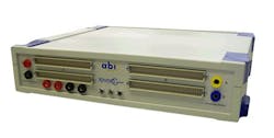
One answer is a system that can recreate circuit schematics, even PCB layouts, of the equipment being maintained or repaired. Although manual point-to-point circuit detection and observation is one solution for trying to re-document the PCB, it is prohibitively time-consuming. However, there is now an easier way, using a product from Europe called RevEngfor REVerse ENGineering (Fig. 1).

This documentation recreation tool supports the increasingly vexing problem for users and maintainers of long life systems where support strategy for spares and repairs are critical issues. This includes water and electricity utilities, medical equipment, military systems, air traffic control, aircraft maintenance, avionics simulation, traffic control, trains, and signaling.
Today, established companies are being taken over, restructured, or go out of business, leading to the growing situation where no support is available. Rapidly changing technology increases the problems of support. Many products quickly become obsolete and are not supported or manufactured long before the end of their true operating life. And, although many consumer products are replaced rather than repaired, this approach cannot be applied to long life systems.
A standard solution from many suppliers is an upgrade to the latest product or its nearest equivalent. But when a product is part of a large system, this solution is unacceptable unless the replacement is physically and functionally identical (form/fit/function). Changing to a new component may entail the expense of recertifying the whole system for critical equipment such as medical diagnostic machines.
The Better Solution
The RevEng System creates professional quality circuit schematic diagrams from a sample PCB that has no documentation. The RevEng System consists of a PC-controlled continuity-detecting hardware system, SYSTEM8 Ultimate control software, and EdWin, a fully featured CAD package. RevEng ‘learns’ the connectivity of the sample circuit, producing a netlist of the components and connections for importing into EdWin software. The result is professional quality circuit diagrams and even new PCB layouts, if required.
RevEng’s learning process is achieved using a selection of clips, connectors, and probes that you attach to components on the board under test. SYSTEM8 Ultimate guides the operator to place and move the clips around the board. SYSTEM8 Ultimate generates an efficient sequence of clip combinations and movements that make it possible to learn all possible connections, but the operator can override the automatic placement of the clips, if necessary.
To minimize operator errors, the system applies an orientation check and pin check to confirm clip contact and position. RevEng completes its learning process without the need for applying power to the board and limits the applied voltage and current so that semiconductor gates are not affected - which also makes it safe to use on low power technologies. You can use the resulting netlist as an input to CAD packages and as data input for ATE programs.
SYSTEM8 Ultimate software controls the system hardware and provides links with the CAD software. Its key features include: Icon-driven operation, context-sensitive help, unlimited number of clips and connectors, partial circuit learn and draw, repeat learn and verify, optimized clip movement, digital or analog circuits, guided probe for non-standard components, suspend/restart/terminated at any stage, etc.
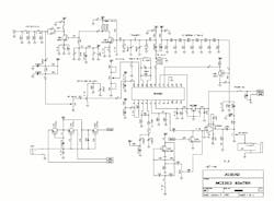
The EdWin professional drawing package enables the fast generation of drawings by importing the netlist and using an automated process to place components and signal routing. The resulting drawings can include bus structures and multi-page schematics. EdWin has capabilities that include features such as: importing the netlist to place components, auto routing signals, multi-page schematics, bus structure support, an extensive library of over 12,000 devices, ‘rubber band’ and ‘rats nest’ functions, block move and rotate, etc. The library includes discrete components, analog and digital ICs, microprocessors, memories, and connectors - but new and custom devices can be easily added without necessarily knowing the function of the device or even which pins are inputs or outputs. Fig. 2 is an actual example of a redrawn circuit diagram.
An enhanced version of the CAD software allows generation of artwork for a circuit board layout, design verification, and simulation. Optional capabilities include Bill of Materials, PCB Layout, Mix-mode simulation, Arizona Autorouter, Thermal Analyzer, EDSpice, EMC + Signal Integrity. Edwin’s special features enable same-day drawings of unknown, complex boards.
Learning Method
There are two major parts to the process: data entry/learn followed by schematic drawing. Node learning and measurement is achieved by means of clips, connectors, and probes that are attached to clusters of components. SYSTEM8 Ultimate software guides the operator to place and move the clips around the reference circuit, measuring the resistance between the component pins. The short circuit threshold is set at 7 Ω. The probes provide 5 V into an open circuit and 10 mA into a short circuit on an unpowered board. Typically the system delivers 10 µA into a circuit. To minimize operator errors, the system applies an orientation check and a pin check to confirm clip contact and position.
SYSTEM8 Ultimate software generates an efficient sequence of clip combinations and movements that will learn all possible connections, but the operator can modify or override the automatic placement of the clips if necessary. RevEnglearns without applying power to the board. It limits the measurement voltage and current. Semiconductor gates and low power technologies are not affected.
It is also possible to learn part of the circuit. Simply define those components to be included in the drawing and follow the standard procedure. You can include part or all of the remainder of the circuit later. RevEng is very accurate: to ensure complete confidence RevEng offers ReScan and Verification procedures.
The RevEng System is available as an entry-level system with 256 measurement channels for low budget or small to medium circuits. For larger, more complex circuit needs, a high pin-count system equipped with up to 2048 channel measurement channels is also available. The advantage of more channels is reduced learning time - a function of the number of components and the number of clips available.
RevEng is already used by a wide range of customers around the world, mainly to generate documentation for the repair of complex and costly PCBs. Most of these boards are irreplaceable: either the original manufacturers are out of business, or they refuse to supply documentation or spare parts - or would charge prohibitively for the service. Where the legacy equipment and spare parts have been discontinued, generating schematics with RevEng has allowed customers to repair and maintain existing working equipment as well as creating new PCBs based on the original design.
While many RevEng customers are either military or government companies, their projects are necessarily confidential. However, a typical case in the private sector comes from Brazil. Eletrograf (http://eletrograf.com.br ) specializes in the maintenance of printing presses manufactured by companies such as Heidelberg, Gutenberg, Roland, etc. They saw RevEng as a viable tool that would allow them to generate the PCB documentation required for repairing as well as reverse engineering obsolete PCBs, solving frequent breakdowns by improving the original design with the addition of more robust components or by daughter boards that would bypass a troubled section on the original PCB. They then started offering this retrofit service as an add-on to their electronics maintenance plans, which proved a very profitable and convenient idea for Eletrograf and their customers.
Some other RevEng customers include: UK MoD, INDRA (Spain, MoD), SENA (Colombia, education), Brazilian Air Force, Turkey Armed Forces, Australia’s Defence Science and Technology Organisation (DSTO), Chilean Navy, Egyptian Navy, INSA (Ethiopia), Dornier, Deutsche Aerospace, Al Taif Technical (UAE, MoD), Telefonica (Argentina), and METRO Sao Paulo.
For additional information contact the Saelig Company of Fairport, NY (www.saelig.com).
Figures
Fig. 1. RevEngfor REVerse ENGineering
Fig. 2. Circuit diagram redrawn by RevEng.
About the Author
Alan Lowne
CEO, Saelig
Alan Lowne is anlectronics engineer and CEO of Saelig Co. Inc., an industrial electronics importing business he started after a long career at Kodak and Johnson & Johnson. He trained as an electronics engineer at Southampton University (UK) and Brunel University (UK) and holds six U.S. patents in optoelectronics.
Comment About the Article
To join the conversation, and become an exclusive member of Electronic Design, create an account today!

Leaders relevant to this article: