Power Supply Characteristics FAQs
How do a power supply’s characteristics affect an electronic system?
A power supply’s characteristics influence the performance and design of an electronic system. Among the important power supply characteristics is efficiency over its specified temperature range. Also, there are important features that protect the power supply and its load from damage, such as output overcurrent, overtemperature, inrush current, and output overvoltage. Then, there are power supply operating parameters such as drift, dynamic response, line regulation, and load regulation that can impact system operation.
Related Articles
- Power Management Basics: Power Supply Fundamentals
- Power Management Basics: Power Supply Characteristics
- Why is it Important to Plot a Power Stage Small-Signal Response?
- Back to Basics: Voltage Regulator ICs Part 1
- Power-Supply Failures Are Mostly Preventable
- Monolithic Regulators Migrate to Higher Voltages
How does power supply efficiency impact electronic system performance?
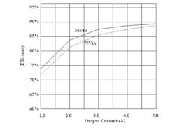
Power supply efficiency determines the thermal and electrical losses in the system, as well as the amount of cooling required. Also, it impacts the physical package sizes of both the power supply and the final end-item system. Plus, it affects the operating temperatures of system components and the resultant system reliability. These factors contribute to the determination of the total system cost, both hardware and field support. Power supply data sheets usually include a plot of efficiency vs. output current, as shown in Fig. 1. This plot shows that efficiency varies with the power supply’s applied voltage as well as the output load current.
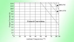
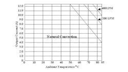
Efficiency, reliability, and operating temperature are inter-related. Power supply data sheets usually include specific airflow and heat sink requirements. For example, the ambient operating temperature affects the output load current that the power supply can handle reliably. Derating curves for the power supply (Fig. 2) indicate its reliable operating current vs. temperature. Fig. 2 shows how much current the supply can be safely handled if it is operating with natural convection, or 200 LFM and 400 LFM.
What operational features protect a power supply?
There are several other characteristics that impact power supply operation. Among these are those employed to protect the supply, including:
Overcurrent: A failure mode caused by output load current that is greater than specified. It is limited by the maximum current capability of the power supply and controlled by internal protection circuits. It can also damage the power supply in some cases. Short circuits between the power supply output and ground can create currents within the system that are limited only by the maximum current capability and internal impedance of the power supply. Without limiting, this high current can cause overheating and damage the power supply as well as the load and its interconnects (pc board traces, cables). Therefore, most power supplies should have current limiting (overcurrent protection) that activates if the output current exceeds a specified maximum.
Overtemperature: A temperature that is above the power supply’s specified limit must be prevented or it can cause power supply failure. Excessive operating temperature can damage a power supply and the circuits connected to it. Therefore, many supplies employ a temperature sensor and associated circuits to disable the supply if its operating temperature exceeds a specific value. In particular, semiconductors used in the supply are vulnerable to temperatures beyond their specified limits. Many supplies include overtemperature protection that turns off the supply if the temperature exceeds the specified limit.
Overvoltage: This failure mode occurs if the output voltage goes above the specified dc value, which can impose excessive dc voltage that damages the load circuits. Typically, electronic system loads can withstand up to 20% overvoltage without incurring any permanent damage. If this is a consideration, select a supply that minimizes this risk. Many supplies include overvoltage protection that turns the supply off if the output voltage exceeds a specified amount. Another approach is a crowbar zener diode that conducts enough current at the overvoltage threshold so that it activates the power supply current limiting and it shuts down .
Soft Start: Inrush current limitation may be needed when power is first applied or when new boards are hot plugged. Typically, this is achieved by a soft-start circuit that slows the initial rise of current and then allows normal operation. If left untreated, the inrush current can generate a high peak charging current that impacts the supply’s output voltage. If this is an important consideration, select a supply with this feature.
Undervoltage Lockout: Known as UVLO, it turns the supply on when it reaches a high enough input voltage and turns off the supply if the input voltage falls below a certain value. This feature is used for supplies operating from utility power as well as battery power. When operated from battery-based power, UVLO disables the power supply (as well as the system) if the battery discharges so much that it drops the supply’s input voltage too low to permit reliable operation.
Power Factor Correction (PFC): Applicable only to ac-dc power supplies. The relationship between the ac power line voltage and current is called power factor. For a purely resistive load on the power line, voltage and current are in phase and the power factor is 1.0. However, when an ac-dc power supply is placed on the power line, the voltage-current phase difference increases and power factor decreases because the process of rectifying and filtering the ac input upsets the relationship between voltage and current on the power line. When this occurs, it reduces power supply efficiency and generates harmonics that can cause problems for other systems connected to the same power line. Power factor correction (PFC) circuits modify the relationship between power line voltage and current, by making them closer to being in phase. This improves the power factor, reduces the harmonics, and improves the power supply’s efficiency. If power line harmonics are important, choose a supply with PFC that has a power factor of 0.9 or higher.
Electromagnetic Compatibility (EMC): Manufactured power supplies must employ design techniques that provide electromagnetic compatibility (EMC) by minimizing electromagnetic interference (EMI). In switch-mode power supplies, a dc voltage is converted to a chopped or a pulsed waveform. This causes the power supply to generate narrow-band noise (EMI) at the fundamental of the switching frequency and its associated harmonics. To mitigate the noise, manufacturers must minimize radiated or conducted emissions.
Power supply manufacturers can minimize EMI radiation by enclosing the supply in a metal box or spray coating the case with a metallic material. Manufacturers also need to pay attention to the internal layout of the supply and the wiring that goes in and out of the supply, which can generate electrical noise.
Most of the conducted interference on the power line is the result of the main switching transistor or output rectifiers. With power factor correction and proper transformer design, connection of the heat sink, and filter design, the power supply manufacturer can reduce conducted interference so that the supply can achieve EMI regulatory agency approvals without incurring excessive filtering cost. Always check to see that the power supply manufacturer meets the requirement of the regulatory EMI standards.
Regulatory Standards
Standards attempt to standardize a product’s EMC performance with respect to EMI. Regulatory standards must be met because international and domestic standards are required for the power management section of the end-item equipment. These standards vary from one country to another, so the power subsystem manufacturer and the end-item system manufacturer must adhere to these standards where the system will be sold. Design engineers must understand these standards even though they may not perform standards certification. Understanding these regulatory standards usually pose problems for power management subsystem designers because:
· Many standards are technically complex, requiring an expert to be able to decipher them.
· Often, standards are written in a form that is difficult for the uninitiated to interpret because there are usually exemptions and exclusions that are not clear.
· Several different agencies may be involved, so some may be specific to one country or group of countries and not others.
· Standard requirements vary and sometimes conflict from one jurisdiction to another.
· Standards are continually evolving, with new ones introduced periodically, so it is difficult to keep pace with them.
What standards agencies are encountered at the product and system level?
1. ANSI: American National Standards Institute oversees the creation, promulgation and use of norms and guidelines that directly impact businesses, including energy distribution
2. EC (European Community) Directives. Companies responsible for the product intended for use in the European Community must design and manufacture it in accordance with the requirements in the relevant directives.
3. EN (European Norm): Standard directives for the European community.
4. IEC (International Electrotechnical Commission): Generates standards for electrical and electronic systems.
5. UL (Underwriter’s Laboratory): Safety approvals for electrical and electronics products within the USA. A UL approval can also be obtained through the CSA.
6. CSA (Canadian Standards Association): Safety approval required to use an electrical or electronic product within Canada. A CSA approval can also be obtained through the UL.
7. Telcordia: Standards for telecom equipment in the USA.
8. ETSI (European Telecommunications Standards Institute): Standards for telecom equipment.
Required safety standards for power supplies contain requirements to prevent injury or damage due to hazards such as: electric shock, energy, fire, mechanical, heat, radiation and chemicals.
Specific standards for power supply acoustics define maximum audible noise levels that may be produced by the product. The main contributor to the acoustic noise is usually the fan in a power supply with an internal fan.
ESD (Electrostatic Discharge) standards test immunity to the effects of high voltage low energy discharges, such as the static charge built up on operating personnel.
About the Author

Sam Davis
Sam Davis was the editor-in-chief of Power Electronics Technology magazine and website that is now part of Electronic Design. He has 18 years experience in electronic engineering design and management, six years in public relations and 25 years as a trade press editor. He holds a BSEE from Case-Western Reserve University, and did graduate work at the same school and UCLA. Sam was the editor for PCIM, the predecessor to Power Electronics Technology, from 1984 to 2004. His engineering experience includes circuit and system design for Litton Systems, Bunker-Ramo, Rocketdyne, and Clevite Corporation.. Design tasks included analog circuits, display systems, power supplies, underwater ordnance systems, and test systems. He also served as a program manager for a Litton Systems Navy program.
Sam is the author of Computer Data Displays, a book published by Prentice-Hall in the U.S. and Japan in 1969. He is also a recipient of the Jesse Neal Award for trade press editorial excellence, and has one patent for naval ship construction that simplifies electronic system integration.
You can also check out his Power Electronics blog.
Comment About the Article
To join the conversation, and become an exclusive member of Electronic Design, create an account today!

Leaders relevant to this article: